
Page 551 - Design and Operation of Heat Exchangers and their Networks
P. 551
534 Appendix
lambda = log10(240 + 0.0002 ∗ Sp) + 0.434 ∗ ...
(2.3 - (343.5 + 0.037 ∗ Sp) / T_68) ...
∗ (1 - T_68 / (647 + 0.03 ∗ Sp)) ^ 0.333;
lambda = 10 ^ lambda / 1000;
mu_water = 4.2844E-5 + 1 / (0.157 ∗ (t + 64.993) ^ 2 - 91.296);
A = (-9.52E-5 ∗ t + 1.998E-2) ∗ t + 1.541;
B = (4.724E-4 ∗ t - 7.561E-2) ∗ t + 7.974;
mu = mu_water ∗ ((B ∗ S+A) ∗ S + 1);
end
% rho: oil density at p = 1 bar, kg/m3
% t: temperature, °C, 0 < t < 180°C
% S: salinity of seawater, kg/kg, 0 < S < 0.16,
function [rho, cp, lambda, mu] = oil_properties (t)
rho = (3.8112E-4 ∗ t - 0.62602) ∗ t + 905.03;
cp = (4.4988E-3 ∗ t + 3.5465) ∗ t + 1835.4;
lambda = 0.14494 - 8.8455E-5 ∗ t;
mu = exp(((-2.0359E-6 ∗ t + 6.1253E-4) ∗ t - 8.9038E-2) ∗ t + 0.1743);
end
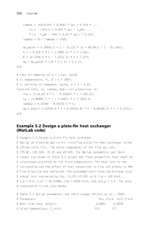
Example 5.2 Design a plate-fin heat exchanger
(MatLab code)
% Example 5.2 Design a plate-fin heat exchanger
% Design an aluminum gas-to-air crossflow plate-fin heat exchanger using
% offset-strip fins. The molar components of the flue gas are:
% 77% N2, 12% CO2, 7% O2 and 4% H2O. The design parameters and their
% ranges are shown in Table 5.2 except the fluid properties that shall be
% calculated according to the fluid temperature. The heat loss to the
% surrounding and the effect of heat conduction in fins and plates in the
% flow direction are neglected. The exchanger shall have the minimum total
% annual cost evaluated by Eqs. (5.97)-(5.99) with C_A = 100 $/m2,
% n_A = 0.6, C_el = 30 $/MWh, tau = 6500 h/yr, and eta_p = 0.5. The area
% reservation is not considered.
% Table 5.2 Design parameters and their ranges (Mishra et al., 2009)
% Parameters Hot fluid Cold fluid
% Mass flow rate, m(kg/s) 0.8962 0.8296
% Inlet temperature, T_in(K) 513 277