Page 548 - Design and Operation of Heat Exchangers and their Networks
P. 548
Appendix  531


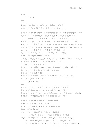
                     else
                          J_r = 1;
                     end
                     % shellside heat transfer coefficient, W/m2K
                     alpha_s = alpha_id ∗ J_c ∗ J_l ∗ J_b ∗ J_s ∗ J_r;

                     % calculation of thermal performance of the heat exchanger, W/m2K
                     k_s =1/(1 / alpha_s + R_f_s + d_o ∗ log(d_o / d_i) / 2 ...
                         / lambda_w_t + d_o / d_i ∗ (R_f_t + 1 / alpha_t));
                     A_s = N_t ∗ pi ∗ d_o ∗ L; % shellside heat transfer area, m2
                     NTU_t = k_s ∗ A_s / (m_t ∗ cp_t); % number of heat transfer units
                     R_t = m_t ∗ cp_t / (m_s ∗ cp_s); % thermal capacity flow rate ratio
                     ss = sqrt(1 + R_t  ^  2+2 ∗ R_t ∗ (2 ∗ ksi - 1));
                     P_t =2/(1 + R_t + ss ∗ coth(NTU_t ∗ ss / 2));
                     % heat exchanger effectiveness
                     Q = P_t ∗ (t_s_in - t_t_in) ∗ m_t ∗ cp_t; % heat transfer rate, W
                     dt_max = t_t_in + Q / (m_t ∗ cp_t) - t_t_out;
                     t_t_out = t_t_out + dt_max;
                     % calculated outlet temperatures of seawater (tubeside), °C
                     dt = t_s_in - Q / (m_s ∗ cp_s) - t_s_out;
                     t_s_out = t_s_out + dt;
                     % calculated outlet temperatures of oil (shellside), °C
                     if (abs(dt_max) < abs(dt))
                          dt_max = dt;
                     end
                     % t_s_w = t_s_m - k_s / alpha_s ∗ (t_s_m - t_t_m);
                     % mean oil temperature at tube outside wall, °C
                     % t_t_w = t_t_m + k_s ∗ d_o / (alpha_t ∗ d_i) ∗ (t_s_m - t_t_m);
                     % mean oil temperature at tube outside wall, °C

                     % calculation of tubeside pressure drop
                     sigma = N_t ∗ (d_i / d_s)  ^  2;
                     % ratio of free flow area to frontal area
                     lnRe_t = log(Re_t);
                     K_c = sigma ∗ (0.02744 / lnRe_t - 0.4016) ...
                         + (9.1465 / lnRe_t - 0.1418) / lnRe_t + 0.4079;
                     CK_e = 2 ∗ sigma ∗ (((19.65 / lnRe_t + 0.6314) / lnRe_t ...
                         + 0.109) / lnRe_t + 1 - sigma) / (1 - (235 / Re_t + 0.01277) ...
                                                                        ^
                         ∗ (1 - sigma  ^  0.25) ∗ (1 - sigma)); % CK_e = 1-sigma 2-K_e

