Page 544 - Design and Operation of Heat Exchangers and their Networks
P. 544
Appendix  527


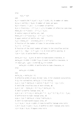
                 else
                      s_t_ = s_d;
                 end
                 N_t = round(0.156 ∗ (d_otl / d_o)  ^  2.291, 0); % number of tubes
                 N_t_p = ceil(N_t / N_p); % number of tubes per pass
                 N_b = floor(L / l_bc) - 1; % number of baffles
                 N_rc = floor((d_s - 2 ∗ l_c) / s_l); % number of effective tube rows
                 theta_ds = 2 ∗ acos(1 - 2 ∗ l_c / d_s);
                 % central angle of baffle cut, rad
                 theta_ctl = 2 ∗ acos((d_s - 2 ∗ l_c) / d_ctl);
                 % upper central of baffle cut, rad
                 F_w = (theta_ctl - sin(theta_ctl)) / (2 ∗ pi);
                 % fraction of the number of tubes in one window section
                 F_c =1-2 ∗ F_w;
                 % fraction of the total number of tubes in the crossflow section
                 l_bi = (L - (N_b - 1) ∗ l_bc) / 2; % inlet baffle spacing, m
                 l_bo = l_bi; % outlet baffle spacing, m

                 delta_st = d_s - d_otl; % shell-to-tube-bundle clearance, m
                 delta_sb = 0.0031 + 0.004 ∗ d_s; % shell-to-baffle clearance, m
                 if (max(l_bi, l_bc) > 0.914 && d_o <= 0.0318)
                     delta_bt = 0.0004; % baffle-hole-to-tube clearance, m
                 else
                     delta_bt = 0.0008;
                 end
                 delta_tp_ = delta_tp / 2;
                 % effective width of pass divider lane. 0 for standard calculation;
                 % d_o for estimation; delta_tp / 2 for rating
                 A_sc = l_bc ∗ (delta_st + sqrt(2) ∗ d_ctl ∗ (1 - d_o / s));
                 % shellside crossflow area of main stream, m2
                 A_sb = (pi - theta_ds / 2) ∗ d_s ∗ delta_sb / 2;
                 % shell-to-baffle leakage area, m2
                 A_bt = pi / 4 ∗ ((d_o + delta_bt)  ^  2 - d_o  ^  2) ∗ N_t ∗ (1 - F_w);
                 % baffle-hole-to-tube leakage area, m2
                 A_bp = l_bc ∗ (delta_st + N_tp ∗ delta_tp_);
                 % shell-to-tube-bundle bypass area, m2
                 r_s = A_sb / (A_sb + A_bt); % tube-to-baffle leakage area ratio
                 r_lm = (A_sb + A_bt) / A_sc; % baffle-to-shell leakage area ratio
                 r_b = A_bp / A_sc; % bypass area ratio

