
Page 543 - Design and Operation of Heat Exchangers and their Networks
P. 543
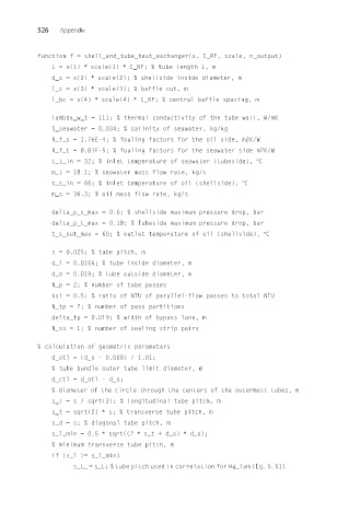
526   Appendix


          function f = shell_and_tube_heat_exchanger(x, C_RF, scale, n_output)
              L = x(1) ∗ scale(1) ∗ C_RF; % tube length L, m
              d_s = x(2) ∗ scale(2); % shellside inside diameter, m
              l_c = x(3) ∗ scale(3); % baffle cut, m
              l_bc = x(4) ∗ scale(4) ∗ C_RF; % central baffle spacing, m

              lambda_w_t = 111; % thermal conductivity of the tube wall, W/mK
              S_seawater = 0.034; % salinity of seawater, kg/kg
              R_f_s = 1.76E-4; % fouling factors for the oil side, m2K/W
              R_f_t = 8.81E-5; % fouling factors for the seawater side m2K/W
              t_t_in = 32; % inlet temperature of seawater (tubeside), °C
              m_t = 18.1; % seawater mass flow rate, kg/s
              t_s_in = 66; % inlet temperature of oil (shellside), °C
              m_s = 36.3; % oil mass flow rate, kg/s
              delta_p_s_max = 0.6; % shellside maximum pressure drop, bar
              delta_p_t_max = 0.18; % Tubeside maximum pressure drop, bar
              t_s_out_max = 60; % outlet temperature of oil (shellside), °C
              s = 0.025; % tube pitch, m
              d_i = 0.0166; % tube inside diameter, m
              d_o = 0.019; % tube outside diameter, m
              N_p = 2; % number of tube passes
              ksi = 0.5; % ratio of NTU of parallel-flow passes to total NTU
              N_tp = 2; % number of pass partitions
              delta_tp = 0.019; % width of bypass lane, m
              N_ss = 1; % number of sealing strip pairs

          % calculation of geometric parameters
              d_otl = (d_s - 0.008) / 1.01;
              % tube bundle outer tube limit diameter, m
              d_ctl = d_otl - d_o;
              % diameter of the circle through the centers of the outermost tubes, m
              s_l = s / sqrt(2); % longitudinal tube pitch, m
              s_t = sqrt(2) ∗ s; % transverse tube pitch, m
              s_d = s; % diagonal tube pitch, m
              s_l_min = 0.5 ∗ sqrt((2 ∗ s_t + d_o) ∗ d_o);
              % minimum transverse tube pitch, m
              if (s_l >= s_l_min)
                   s_t_ = s_t; % tube pitch used in correlation for Hg_lam (Eq. 5.51)