
Page 122 - Design for Six Sigma a Roadmap for Product Development
P. 122
Product Development Process and Design for Six Sigma 97
Y=f(x)
Matrix A
CAs FRs DPs PVs
• • • •
• • • •
• • • •
Y=f(x) Matrix B
Physical mapping Process mapping
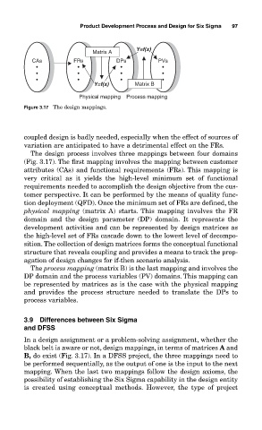
Figure 3.17 The design mappings.
coupled design is badly needed, especially when the effect of sources of
variation are anticipated to have a detrimental effect on the FRs.
The design process involves three mappings between four domains
(Fig. 3.17). The first mapping involves the mapping between customer
attributes (CAs) and functional requirements (FRs). This mapping is
very critical as it yields the high-level minimum set of functional
requirements needed to accomplish the design objective from the cus-
tomer perspective. It can be performed by the means of quality func-
tion deployment (QFD). Once the minimum set of FRs are defined, the
physical mapping (matrix A) starts. This mapping involves the FR
domain and the design parameter (DP) domain. It represents the
development activities and can be represented by design matrices as
the high-level set of FRs cascade down to the lowest level of decompo-
sition. The collection of design matrices forms the conceptual functional
structure that reveals coupling and provides a means to track the prop-
agation of design changes for if-then scenario analysis.
The process mapping (matrix B) is the last mapping and involves the
DP domain and the process variables (PV) domains. This mapping can
be represented by matrices as is the case with the physical mapping
and provides the process structure needed to translate the DPs to
process variables.
3.9 Differences between Six Sigma
and DFSS
In a design assignment or a problem-solving assignment, whether the
black belt is aware or not, design mappings, in terms of matrices A and
B, do exist (Fig. 3.17). In a DFSS project, the three mappings need to
be performed sequentially, as the output of one is the input to the next
mapping. When the last two mappings follow the design axioms, the
possibility of establishing the Six Sigma capability in the design entity
is created using conceptual methods. However, the type of project