
Page 290 - Design for Six Sigma a Roadmap for Product Development
P. 290
260 Chapter Eight
4. Reorder and categorize design matrices at all levels as coupled,
decoupled, or uncoupled.
5. Maintain independence of FRs at all levels of physical structure by
employing the methods presented in this section.
6. Repeat steps 1 to 5 in the process mapping (the mapping from DPs
to PVs).
8.5.4 The decoupling phase
(DFSS algorithm 6.2)
This example is a continuation to Fig. 8.10 of Sec. 8.4.3, where the
mapping of x 1 “displacement mechanism” is depicted.
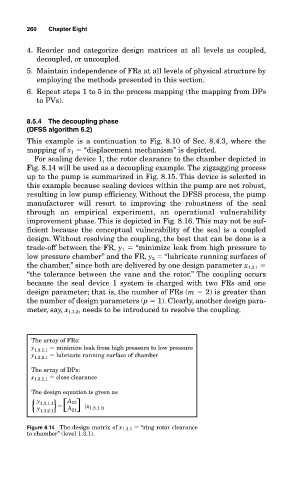
For sealing device 1, the rotor clearance to the chamber depicted in
Fig. 8.14 will be used as a decoupling example. The zigzagging process
up to the pump is summarized in Fig. 8.15. This device is selected in
this example because sealing devices within the pump are not robust,
resulting in low pump efficiency. Without the DFSS process, the pump
manufacturer will resort to improving the robustness of the seal
through an empirical experiment, an operational vulnerability
improvement phase. This is depicted in Fig. 8.16. This may not be suf-
ficient because the conceptual vulnerability of the seal is a coupled
design. Without resolving the coupling, the best that can be done is a
trade-off between the FR, y 1 “minimize leak from high pressure to
low pressure chamber” and the FR, y 2 “lubricate running surfaces of
the chamber,” since both are delivered by one design parameter x 1.3.1
“the tolerance between the vane and the rotor.” The coupling occurs
because the seal device 1 system is charged with two FRs and one
design parameter; that is, the number of FRs (m 2) is greater than
the number of design parameters (p 1). Clearly, another design para-
meter, say, x 1.3.2 , needs to be introduced to resolve the coupling.
The array of FRs:
y minimize leak from high pressure to low pressure
1.3.1.1
y lubricate running surface of chamber
1.3.2.1
The array of DPs:
x 1.3.1.1 close clearance
The design equation is given as
y
1.3.1.1 A 12
{ y 1.3.2.1 } [ ]A 21 {x 1.3.1.1}
Figure 8.14 The design matrix of x 1.3.1 “ring rotor clearance
to chamber” (level 1.3.1).