
Page 286 - Design for Six Sigma a Roadmap for Product Development
P. 286
256 Chapter Eight
y 1 A A 12 A 13 0 x 1
11
y 2 = A 21 A 0 0 x 2
22
y 3 A 31 0 0 0 x 3
y 4 A 41 A 42 A 43 A 44 x 4
Adjustment Sequence:
DPs Objective Effects
Reordering x 1 y 3 y , y , y 4
1
2
x 2 y 2 y , y 4
1
x 3 y 1 y 4
x 4 y 4 –
y 3 A 31 0 0 0 x 1
y 2 = A 21 A 0 0 x 2
22
y 1 A A 12 A 13 0 x 3
11
y 4 A 41 A 42 A 43 A 44 x 4
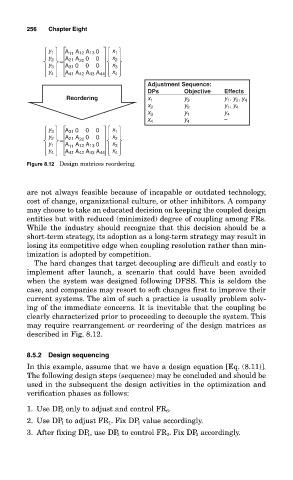
Figure 8.12 Design matrices reordering.
are not always feasible because of incapable or outdated technology,
cost of change, organizational culture, or other inhibitors. A company
may choose to take an educated decision on keeping the coupled design
entities but with reduced (minimized) degree of coupling among FRs.
While the industry should recognize that this decision should be a
short-term strategy, its adoption as a long-term strategy may result in
losing its competitive edge when coupling resolution rather than min-
imization is adopted by competition.
The hard changes that target decoupling are difficult and costly to
implement after launch, a scenario that could have been avoided
when the system was designed following DFSS. This is seldom the
case, and companies may resort to soft changes first to improve their
current systems. The aim of such a practice is usually problem solv-
ing of the immediate concerns. It is inevitable that the coupling be
clearly characterized prior to proceeding to decouple the system. This
may require rearrangement or reordering of the design matrices as
described in Fig. 8.12.
8.5.2 Design sequencing
In this example, assume that we have a design equation [Eq. (8.11)].
The following design steps (sequence) may be concluded and should be
used in the subsequent the design activities in the optimization and
verification phases as follows:
1. Use DP 6 only to adjust and control FR 6 .
2. Use DP 1 to adjust FR 1 . Fix DP 1 value accordingly.
3. After fixing DP 1 , use DP 3 to control FR 3 . Fix DP 3 accordingly.