
Page 282 - Design for Six Sigma a Roadmap for Product Development
P. 282
252 Chapter Eight
The array of FRs:
y 1.1 charge chamber
y 1.2 discharge chamber at uniform rate
y 1.3 does not allow slip flow to pass from outlet to inlet
y 1.4 provides displacement charge based on external hydraulic signal
The array of DPs:
x 1.1 expanding chamber
x 1.2 collapsing volumes
x 1.3 sealing device—geometry boundary between inlet and outlet
x 1.4 movable bore ring
x 1.5 bias spring
x 1.6 control pressure
x 1.7 rigid cover
x 1.8 rigid body
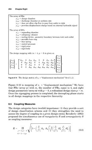
The design mapping with (m 4, p 8) is given as x 1.1
y 1.1 A 11 0 A 13 A 14 0 0 A 17 A 18 x 1.2
x 1.3
x 1.4
y 1.2 0 A 22 A 23 0 0 A 26 A 27 A 28 ] {}
y 1.3 0 0 A 33 0 0 0 A 37 A 38 x 1.5
{ }[ 0 0 A 43 A 44 A 45 A 46 A 47 A 48 x 1.6
y 1.4
x 1.7
x 1.8
Figure 8.10 The design matrix of x 1 “displacement mechanism” (level 1.1).
Figure 8.10 is mapping of x 1 “displacement mechanism.” We have
four FRs (array y) with m, the number of FRs, equal to 4, and eight
design parameters (array x) with p 8, a redundant design since p m.
Once the zigzagging process is completed, the decoupling phase starts
in all design mappings in the respective hierarchy.
8.5 Coupling Measures
The design categories have twofold importance: (1) they provide a sort
of design classification scheme and (2) they strengthen the need to
assess the degree of coupling in a given design entity. Reinderle (1982)
proposed the simultaneous use of reangularity R and semangularity S
as coupling measures:
p 2 p p
2
R
A kj A kj
A kj
A kj
1
2
j 1, p 1 i 1 k 1 k 1 (8.6)
k 1 i, p