
Page 281 - Design for Six Sigma a Roadmap for Product Development
P. 281
Axiomatic Design 251
engine starts. Movement of the slide against the spring occurs when
the pump pressure regulator valve reaches its predetermined value.At the
design regulating point, the pressure regulator valve opens a port feed
to the pump slide and results in a slide movement against the priming
spring to cut back on volume delivery and maintain regulated pressure.
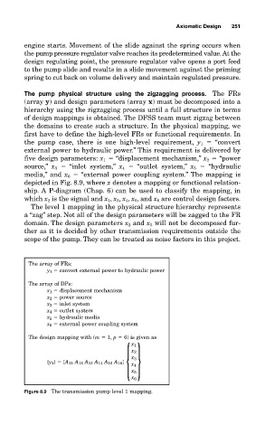
The pump physical structure using the zigzagging process. The FRs
(array y) and design parameters (array x) must be decomposed into a
hierarchy using the zigzagging process until a full structure in terms
of design mappings is obtained. The DFSS team must zigzag between
the domains to create such a structure. In the physical mapping, we
first have to define the high-level FRs or functional requirements. In
the pump case, there is one high-level requirement, y 1 “convert
external power to hydraulic power.” This requirement is delivered by
five design parameters: x 1 “displacement mechanism,” x 2 “power
source,” x 3 “inlet system,” x 4 “outlet system,” x 5 “hydraulic
media,” and x 6 “external power coupling system.” The mapping is
depicted in Fig. 8.9, where x denotes a mapping or functional relation-
ship. A P-diagram (Chap. 6) can be used to classify the mapping, in
which x 2 is the signal and x 1 , x 3 , x 4 , x 5 , and x 6 are control design factors.
The level 1 mapping in the physical structure hierarchy represents
a “zag” step. Not all of the design parameters will be zagged to the FR
domain. The design parameters x 2 and x 5 will not be decomposed fur-
ther as it is decided by other transmission requirements outside the
scope of the pump. They can be treated as noise factors in this project.
The array of FRs:
y 1 convert external power to hydraulic power
The array of DPs:
x 1 displacement mechanism
x 2 power source
x 3 inlet system
x 4 outlet system
x 5 hydraulic media
x 6 external power coupling system
The design mapping with (m 1, p 6) is given as
{}
x 1
x 2
x 3
{y 1} [A 11 A 12 A 13 A 14 A 15 A 16] x 4
x 5
x 6
Figure 8.9 The transmission pump level 1 mapping.