
Page 279 - Design for Six Sigma a Roadmap for Product Development
P. 279
Axiomatic Design 249
8.4.3 Transmission vane oil pump
The transmission zigzagging exercise, in particular, FR 5.3 pump
pressure control, is continued at the pump level in this example
(Brejcha 1982).
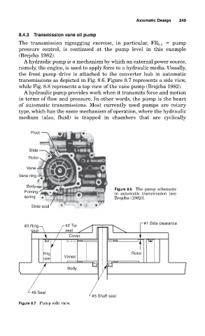
A hydraulic pump is a mechanism by which an external power source,
namely, the engine, is used to apply force to a hydraulic media. Usually,
the front pump drive is attached to the converter hub in automatic
transmissions as depicted in Fig. 8.6. Figure 8.7 represents a side view,
while Fig. 8.8 represents a top view of the vane pump (Brejcha 1982).
A hydraulic pump provides work when it transmits force and motion
in terms of flow and pressure. In other words, the pump is the heart
of automatic transmissions. Most currently used pumps are rotary
type, which has the same mechanism of operation, where the hydraulic
medium (also, fluid) is trapped in chambers that are cyclically
Pivot
Slide
Rotor
Vane
Vane ring
Body
Priming Figure 8.6 The pump schematic
in automatic transmission [see
spring Brejcha (1982)].
Slide seal
#1 Side clearance
#3 Ring #2 Tip
seal seal
Cover
Ring Rotor
Vanes
bore
Body
#9 Seal
#5 Shaft seal
Figure 8.7 Pump side view.