
Page 373 - Design for Six Sigma a Roadmap for Product Development
P. 373
Theory of Inventive Problem Solving (TRIZ) 343
TRIZ methodology, a coupled design is defined as the existence of a
contradiction. Removal of dependency of coupling means to overcome a
technical or physical contradiction by applying inventive principles or
separation principles. Thus, these principles can serve, with AD corol-
laries and theorems, as the guidelines of decoupling a coupled design.
The design process of the paper-handling mechanism (Sekimoto and
Ukai 1994) illustrates how separation principles in TRIZ assist in sat-
isfying axiom 1 in AD.
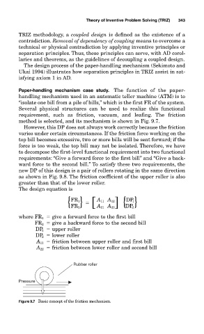
Paper-handling mechanism case study. The function of the paper-
handling mechanism used in an automatic teller machine (ATM) is to
“isolate one bill from a pile of bills,” which is the first FR of the system.
Several physical structures can be used to realize this functional
requirement, such as friction, vacuum, and leafing. The friction
method is selected, and its mechanism is shown in Fig. 9.7.
However, this DP does not always work correctly because the friction
varies under certain circumstances. If the friction force working on the
top bill becomes excessive, two or more bills will be sent forward; if the
force is too weak, the top bill may not be isolated. Therefore, we have
to decompose the first-level functional requirement into two functional
requirements: “Give a forward force to the first bill” and “Give a back-
ward force to the second bill.” To satisfy these two requirements, the
new DP of this design is a pair of rollers rotating in the same direction
as shown in Fig. 9.8. The friction coefficient of the upper roller is also
greater than that of the lower roller.
The design equation is
FR 1 A 11 A 12 ] { }
DP 1
FR 2 DP 2
{ } [ A 21 A 22
where FR 1 give a forward force to the first bill
FR 2 give a backward force to the second bill
DP 1 upper roller
DP 2 lower roller
A 11 friction between upper roller and first bill
A 22 friction between lower roller and second bill
Rubber roller
Pressure
Figure 9.7 Basic concept of the friction mechanism.