Page 376 - Design for Six Sigma a Roadmap for Product Development
P. 376

346   Chapter Nine


                    Bills  Press Plate

                                         Pressure
           Floor guide


                                                        Pressure


                                                        Gate roller
               Drive roller


                                                             Carriage pinch roller
                         Partial rubber
                         roller
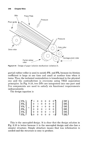
           Figure 9.10 Design of paper isolation mechanism (solution 2).


           partial rubber roller is used to satisfy FR 1 and FR 6 because its friction
           coefficient is large at one time and small at another time when it
           turns. Thus, the technical contradiction is transformed to the physical
           one and the contradiction is overcome using  TRIZ separation
           principles. In Fig. 9.10, two DPs are integrated into one part and
           five components are used to satisfy six functional requirements
           independently.
             The design equation is


                     { } [        
   0  0   0  0   0 ] { }
                       FR 1
                                                              DP 1
                                                0
                                  0
                                      
 0
                                             0
                                                    0
                       FR 2
                                                              DP 2
                                         
 0
                                                    0
                                                0
                                      0
                                  0
                       FR 3
                                                              DP 3

                                                    0
                                             
 0
                                  0
                                      0
                                         0
                                                              DP 4
                       FR 4
                                  0
                       FR 5

                                         0
                                      0
                                  0   0  0   0  
 0           DP 5
                                                0
                                             0
                       FR 6                                   DP 6
             This is the uncoupled design. It is clear that the design solution in
           Fig. 9.10 is better because it is the uncoupled design and also has a
           simpler structure. Simple structure means that less information is
           needed and the structure is easy to produce.
   371   372   373   374   375   376   377   378   379   380   381