
Page 266 - Design for Six Sigma for Service (Six SIGMA Operational Methods)
P. 266
Theory of Inventive Problem Solving (TRIZ) 235
SS 4 height adjustment
(angle-adjusted mirror)
SS focusing device
3
(rack and pinion)
SS magnifying lens
2
SS projection lamp
1
SS cooling fan
5
power supply
SS 6
regulator
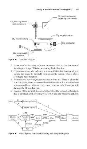
Figure 9.2 Overhead Projector
2. From hand to focusing adjuster to mirror, that is, the function of
focusing the image. This is a secondary basic function.
3. From hand to angular adjuster to mirror, that is, the function of pro-
jecting the image to the right position on the screen. This is also a
secondary basic function.
4. From electric power to projection lamp to lens, etc. There is a harmful
function chain, there are several harmful functions that are all related
to unwanted heat, without correction, these harmful functions will
damage the film and device.
5. Because of the harmful function, we have to add a supporting function,
that is the chain from electric power to fan and end with lens and film.
M
Hand Focusing adjuster
M
M
Angular adjuster
M
Heat
E Light Light Focused
Electric E Projection Heat Heat Image
power lamp Lens Film Mirror Screen
E Cold air
Cold air
Cold air
Fan
Figure 9.3 Whole System Functional Modeling and Analysis Diagram