
Page 191 - Design of Reinforced Masonry Structures
P. 191
DESIGN OF REINFORCED MASONRY BEAMS 4.55
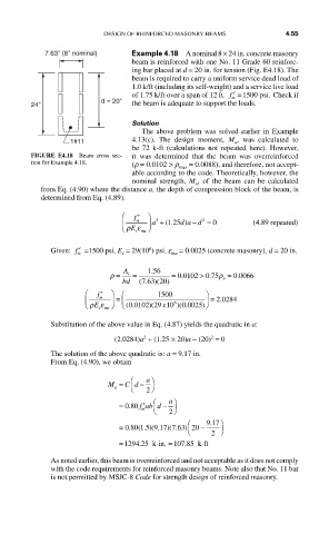
7.63" (8" nominal) Example 4.18 A nominal 8 × 24 in. concrete masonry
beam is reinforced with one No. 11 Grade 60 reinforc-
ing bar placed at d = 20 in. for tension (Fig. E4.18). The
beam is required to carry a uniform service dead load of
1.0 k/ft (including its self-weight) and a service live load
of 1.75 k/ft over a span of 12 ft. ′ =f 1500 psi. Check if
d = 20" m
24" the beam is adequate to support the loads.
Solution
The above problem was solved earlier in Example
1#11 4.13(c). The design moment, M , was calculated to
u
be 72 k-ft (calculations not repeated here). However,
FIGURE E4.18 Beam cross sec- it was determined that the beam was overreinforced
tion for Example 4.18. (r = 0.0102 > r = 0.0088), and therefore, not accept-
max
able according to the code. Theoretically, however, the
nominal strength, M , of the beam can be calculated
n
from Eq. (4.90) where the distance a, the depth of compression block of the beam, is
determined from Eq. (4.89).
⎛ ′ f ⎞
⎜ m ⎟ a 2 + 125( . d a ) − d 2 = 0 (4.89 repeated)
ρε
⎝ E smu ⎠
6
Given: ′ f =1500 psi, E = 29(10 ) psi, e = 0.0025 (concrete masonry), d = 20 in.
m s mu
.
ρ = A s = 156 = 0 0102. > 0 75. ρ = 0 0066.
763 20)
bd (. ) ( b
⎛ ′ f f ⎞ ⎛ 1500 ⎞
m
⎜ ⎝ ρε ⎟ = ⎜ ⎝ ( . )( x10 )( . ) ⎟ = . 2 0284
smu ⎠
0 0025)⎠
6
E
0 0102 29
Substitution of the above value in Eq. (4.87) yields the quadratic in a:
2
2
(2.0284)a + (1.25 × 20)a − (20) = 0
The solution of the above quadratic is: a = 9.17 in.
From Eq. (4.90), we obtain
⎛ a ⎞
M = C d − ⎠ 2
⎝
n
⎛ a ⎞
′
= 080. fab d −
m ⎝ ⎠ 2
⎛ 917 ⎞
.
= 080 15 9.117 7 63 20 −
.
( . )(
)( . )
⎝ 2 ⎠
= 1294 25 k-in . = 107 85 k--ft
.
.
As noted earlier, this beam is overreinforced and not acceptable as it does not comply
with the code requirements for reinforced masonry beams. Note also that No. 11 bar
is not permitted by MSJC-8 Code for strength design of reinforced masonry.