
Page 193 - Design of Reinforced Masonry Structures
P. 193
DESIGN OF REINFORCED MASONRY BEAMS 4.57
to be obtained from linear interpolation of the values given by Eqs. (4.92) and (4.93).
Note that as the value of ratio M /V d increases from 0.25 to 1.00, the maximum value
u v
u
of V decreases by one-third.
n
It is noteworthy that limitations for V given by Eqs. (4.92) and (4.93) were derived for
n
shear walls, which act as vertical beams. For transversely loaded beams, the ratio M /V d
u v
u
would almost always be greater than 1.0, and Eq. (4.93) would apply.
Shear cracking in masonry is caused primarily by diagonal tension. The last term in
Eq. (4.91) (expressed as 0.25P ) provides for the influence of axial compressive force that
u
may be present in the member (e.g., a prestressed masonry beam or a shear wall subjected
to gravity loads), which tends to counteract the horizontal component of diagonal tension
in the beam. MSJC-08 Section 3.3.4.2.1 specifies an upper limit of the factored axial load
P in a beam [to be included in Eq. (4.91)] as given by the following expression:
u
P 0.05A f ′ (4.94)
u n m
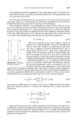
The term d included in Eq. (4.91) whether it should be
v
equal to h or d, remains debatable. This term is intended to be
used for shear walls, which act as vertical beams, and which
also carry a significant amount of factored load P (due to
u
h d = d v gravity loads). In the case of a shear wall, d represents the
v
length of the wall measured parallel to the horizontal shear
force it is designed to resist. In a shear wall, the difference
A s between distances d and d (the distance between the extreme
v
compression fibers and the centroid of tension reinforcement)
is relatively negligible (i.e., d ≈ d). However, such is not the
v
case in a transversely loaded beam. The difference between
FIGURE 4.10 Definitions
of d and d v for beams. the two terms (dimensions h and d) is illustrated in Fig. 4.10
for clarity. Therefore, when applying Eq. (4.91) to transversely
loaded beams, d should be replaced with d, the distance from the extreme compression
v
fibers to the centroid of tension reinforcement (the same as used for flexural calculations, a
conservative approach used in this book (see Examples 4.14 and 4.15). Thus, for transversely
loaded members such as beams and lintels, Eq. (4.91) can be rewritten as follows:
⎡ ⎛ M ⎞ ⎤
V = ⎢ 40 175. − . ⎜ u ⎟ ⎥ A f ′ + 025. P (4.95)
nm ⎝ Vd ⎠ n m u
⎣ u v ⎦
In transversely loaded beams, the value of ratio M /V d would more likely be greater
u u v
than 1.0, in which case M /V d = 1.0 in Eq. (4.95). Therefore, if P = 0, Eq. (4.95) can be
u u u
expressed as
⎡ ⎛
u
⎟
V = ⎢40 175. − . ⎜ M ⎞ ⎤ ⎥ A f ′
nm ⎝ n m
⎣ ⎢ Vd ⎠ ⎥
v ⎦
u
−
= 41.775 1 0(. )]A f ′
[
n m
= 225A f ′ (4.96)
.
n m
Equation (4.96) gives the value of shear contribution of masonry alone in a transversely
loaded beam. Note that the nominal shear strength of masonry is proportional to the square
root of the specified compressive strength of masonry ′ f . As a result, the nominal shear
m
strength of masonry increases only moderately when ′ f is increased even by as much as 30
m
percent. See Example 4.19.