
Page 198 - Design of Reinforced Masonry Structures
P. 198
4.62 CHAPTER FOUR
where A = cross-sectional area of shear reinforcement (single transverse bars)
v
s = spacing of shear reinforcement
f = yield strength of shear reinforcement
y
d = depth of member measured for the extreme compression fibers to the centroid
of tension reinforcement
In a design situation, the quantity V is obtained from Eq. (4.100), and we need to deter-
ns
mine either the area of shear reinforcement (A ), or the spacing of shear reinforcement (s).
v
In a typical concrete masonry construction, it is required to provide shear reinforcement in
the form of single-legged vertical stirrups placed in individual cells which are later grouted
solid (this is mandatory requirement per MSJC-08 Section. 3.3.4.2.4). Thus, the spacing of
stirrups would be a multiple of cell spacing. For example, in typical 8 × 8 × 16-in. block
masonry, the cells are spaced at 8 in. on center; therefore, the stirrup spacing would be a
multiple of 8 in. (i.e., 8, 16, 24 in., etc.). In a two-wythe clay (brick) masonry construction,
the shear reinforcement can be placed at the desired spacing in the cavity between the two
wythes. In both cases, Eq. (4.101) can be used in one of the two ways:
1. To determine the spacing (s) for a chosen A (cross-sectional area of shear reinforc-
v
ing bar):
Af d
s = vy (4.102)
2 V ns
2. To determine A for a chosen shear reinforcement spacing (s):
v
(
A = 2 Vs) (4.103)
ns
v
fd
y
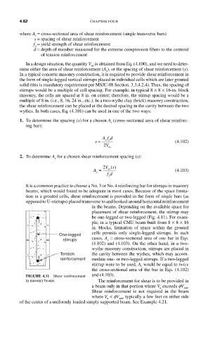
It is a common practice to choose a No. 3 or No. 4 reinforcing bar for stirrups in masonry
beams, which would found to be adequate in most cases. Because of the space limita-
tion in a grouted cells, shear reinforcement is provided in the form of single bars (as
opposed to U-stirrups) placed transverse to and hooked around horizontal reinforcement
in the beams. Depending on the available space for
placement of shear reinforcement, the stirrup may
be one-legged or two-legged (Fig. 4.11). For exam-
ple, in a typical CMU beam built from 8 × 8 × 16
in. blocks, limitation of space within the grouted
One-legged cells permits only single-legged stirrups. In such
stirrups cases, A = cross-sectional area of one bar in Eqs.
v
(4.102) and (4.103). On the other hand, in a two-
wythe masonry construction, stirrups are placed in
Tension the cavity between the wythes, which may accom-
reinforcement modate one- or two-legged stirrups. If a two-legged
stirrup were to be used, A would be equal to twice
v
the cross-sectional area of the bar in Eqs. (4.102)
FIGURE 4.11 Shear reinforcement and (4.103).
in masonry beams. The reinforcement for shear is to be provided in
a beam only in that portion where V exceeds fV .
nm
u
Shear reinforcement is not required in the beam
where V < fV , typically a few feet on either side
u
nm
of the center of a uniformly loaded simply supported beam. See Example 4.21.