
Page 203 - Design of Reinforced Masonry Structures
P. 203
DESIGN OF REINFORCED MASONRY BEAMS 4.67
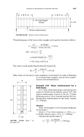
4" 4"
5 @ 8" o/c 5 @ 8" o/c
#3 single-legged
stirrups d = 20"
Tension reinforcement
FIGURE E4.23B Details of shear reinforcement.
* Flexural adequacy of the beam in this example can be quickly checked as follows:
Af (. ) (
079 60)
a = sy = = 5.118 in.
08 fb ′ (. ) ( . ) (.
08 15 763)
.
m
⎛ a ⎞
φM = φA f ⎝ d − 2 ⎠
s y
n
.
09 079 60 20 −
= (. )( . )( ) ⎛ 5 518 ⎞
⎝ 2 ⎠
= 742 7 k-in. = 61 9 k-ft
.
.
This value is much greater than the factored moment M :
u
30 12)
M = wL 2 = (. ) ( 2 = 54 k-ft
u
8 8
Other checks for the beam’s code compliance would need to be made as illustrated
in several previous examples, and are left as readers’
exercise (not performed here).
9"
Example 4.24 Shear reinforcement for a
brick beam.
A 9 × 24 in. brick lintel carries a factored gravity
load of 2.136 k/ft over an effective span of 16 ft. The
tension reinforcement consists of one No. 9 Grade
60 bar placed at d = 20 in. from the top (Fig. E4.24a).
20" Design shear reinforcement for this beam. Assume
24" m ′ f = 2500 psi.
Solution
(Note: See Example 4.14 for flexural calculations
for this beam.)
Given: b = 9 in. (brick masonry), d = 20 in., w =
u
2.136 k/ft, effective span = 16 ft, ′ f = 2500 psi.
m
Calculate the factored shear V .
1#9 u
wl (. ) (
2 136 16)
FIGURE E4.24A Beam for V = u = = 17 09 kips
.
Example 4.24. u 2 2