
Page 200 - Design of Reinforced Masonry Structures
P. 200
4.64 CHAPTER FOUR
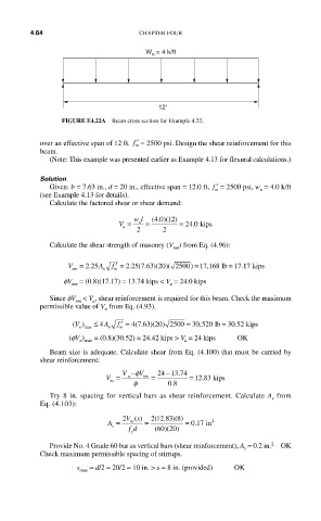
W u = 4 k/ft
12'
FIGURE E4.22A Beam cross section for Example 4.22.
over an effective span of 12 ft. ′ f = 2500 psi. Design the shear reinforcement for this
m
beam.
(Note: This example was presented earlier as Example 4.13 for flexural calculations.)
Solution
Given: b = 7.63 in., d = 20 in., effective span = 12.0 ft, ′ f = 2500 psi, w = 4.0 k/ft
m u
(see Example 4.13 for details).
Calculate the factored shear or shear demand:
40 12)
u
V = wl = (.) ( = 24 0.kips
u
2 2
Calculate the shear strength of masonry (V ) from Eq. (4.96):
nm
V = 2 25 A n f ′ = 2 25 7 63 20)( 2500) = 17 168 lbb = 17 17 kips
(
,
.
.
.
.
)(
nm
m
fV = (0.8)(17.17) = 13.74 kips < V = 24.0 kips
u
nm
Since fV < V , shear reinforcement is required for this beam. Check the maximum
u
nm
permissible value of V from Eq. (4.93).
n
() max ≤ 4 A n f ′ = 4 ( . )(20 ) 2500 = 30 ,520 lb = 30..52 kips
V
63
7
m
n
(fV ) = (0.8)(30.52) = 24.42 kips > V = 24 kips OK
n max
u
Beam size is adequate. Calculate shear from Eq. (4.100) that must be carried by
shear reinforcement:
V −φ V 24 −13 74
.
V = φ 08 .
u nm = = 12 83 kips
.
ns
Try 8 in. spacing for vertical bars as shear reinforcement. Calculate A from
v
Eq. (4.103):
( . )(
A = 2 Vs () = 2 12 83 8) = 017 in 2
ns
.
v
)(
fd ( 60 20)
y
2
Provide No. 4 Grade 60 bar as vertical bars (shear reinforcement), A = 0.2 in. OK
v
Check maximum permissible spacing of stirrups.
s max = d/2 = 20/2 = 10 in. > s = 8 in. (provided) OK