
Page 199 - Design of Reinforced Masonry Structures
P. 199
DESIGN OF REINFORCED MASONRY BEAMS 4.63
4.10.5 MSJC Provisions for Transverse (Shear) Reinforcement
In reinforced masonry beams, transverse reinforcement is required when the shear
demand (V ) exceeds fV . In such cases, MSJC-08 Section 3.3.4.2.3 specifies the fol-
n
u
lowing requirements:
1. Transverse reinforcement shall be a single bar with a 180° hook at each end.
2. Transverse reinforcement shall be hooked around the longitudinal reinforcement.
3. Shear reinforcement shall extend the depth of the member less cover distances.
4. The minimum area of transverse reinforcement shall be 0.0007bd (0.0007bd for
v
shear walls).
5. The first transverse bar shall not be located more than one-fourth of the beam depth d
(d for shear walls) from the end of the beam.
v
6. The maximum spacing of transverse reinforcement shall not exceed one-half of the
beam depth or 48 in.
There are many practical reasons that form the basis of above requirements. Hooking
the transverse reinforcement around the longitudinal bars facilitates construction, confines
the longitudinal reinforcement, and helps ensure the development of the shear reinforce-
ment. The minimum area of shear reinforcement is intended to prevent brittle shear failures.
The limitations on the maximum spacing of shear reinforcement are intended to increase
member ductility.
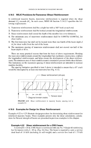
The spacing limitation specified in item 5 above is intended to ensure that a 45° crack
would be intercepted by at least one transverse bar (Fig. 4.12).
Shear reinforcement (stirups)
d
h
s > d/2
Tension steel
Diagonal tension cracks
FIGURE 4.12 Shear reinforcement in masonry beams; spacing not to
exceed d / 2.
4.10.6 Examples for Design for Shear Reinforcement
Examples 4.22 to 4.25 illustrate design procedure for determining shear reinforcement for
reinforced masonry beams. These examples present only the shear calculations; calcula-
tions for flexural strength of beams are presented in previous examples in this chapter.
Example 4.22 Shear reinforcement for a CMU beam.
A nominal 8 × 24 in. CMU beam is reinforced with one No. 9 Grade 60 reinforcing
bar for tension with d = 20 in. (Fig. E4.22a). The beam is required to carry a service
dead load of 1.0 k/ft (including its self-weight) and a service live load of 1.75 k/ft