
Page 201 - Design of Reinforced Masonry Structures
P. 201
DESIGN OF REINFORCED MASONRY BEAMS 4.65
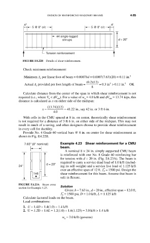
4" 4"
5 @ 8" o/c 5 @ 8" o/c
#4 single-legged
stirrups d = 20"
Tension reinforcement
FIGURE E4.22B Details of shear reinforcement.
Check minimum reinforcement:
Minimum A per linear foot of beam = 0.0007bd = 0.0007(7.63)(20) = 0.11 in. 2
v
2
1
(. )( )
02
2
Actual A provided per foot length of beam = = 0.3 in 2 > . 011 in. OK
v
8
Calculate distance from the center of the span in which shear reinforcement is not
required (i.e., where V < fV ). For a value of w = 4.0 k/ft and fV = 13.74 kips, this
u nm u nm
distance is calculated as x on either side of the midspan:
x = (13 74 12. )( ) = 41 22 in., say 42 in. or 3 ft 6 in.
.
40
.
With cells in the CMU spaced at 8 in. on center, theoretically shear reinforcement
is not required for a distance of 3 ft 6 in. on either side of the midspan. This may not
result in much of a saving, and often designers choose to provide shear reinforcement
in every cell for ductility.
Provide No. 4 Grade 60 vertical bars @ 8 in. on center for shear reinforcement as
shown in Fig. E4.22B.
7.63'' (8'' nominal) Example 4.23 Shear reinforcement for a CMU
beam.
A nominal 8 × 24 in. simply supported CMU beam
is reinforced with one No. 8 Grade 60 reinforcing bar
for tension with d = 20 in. (Fig. E4.23A). The beam is
required to carry a service dead load of 1.0 k/ft (includ-
d = 20''
24'' ing its self-weight) and a service live load of 1.125 k/ft
over an effective span of 12 ft. ′ f = 1500 psi. Design the
m
1#8 shear reinforcement for this beam. Assume that beam is
safe in flexure.
FIGURE E4.23A Beam cross
section for Example 4.23. Solution
Given: b = 7.63 in., d = 20 in., effective span = 12.0 ft,
′ f = 1500 psi, D = 1.0 k/ft, L = 1.125 k/ft
m
Calculate factored loads on the beam.
Load combinations:
1. U = 1.4D = 1.4(1.0) = 1.4 k/ft
2. U = 1.2D + 1.6L = 1.2(1.0) + 1.6(1.125) = 3.0 k/ft > 1.4 k/ft
w = 3.0 k/ft (governs)
u