
Page 206 - Design of Reinforced Masonry Structures
P. 206
4.70 CHAPTER FOUR
b
ε m = 0.0025 0.80 f′ m
d′ ε′ s C s d′ a
2
c A′ s a
c C m
d a
d –
M n
2
d – c
A s T = A s f y
ε = ε y = 0.002
s
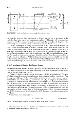
FIGURE 4.13 Strain distribution and forces in a doubly reinforced beam.
considerably. However, their contribution to flexural strength can be accounted for by
including them in the analysis, in which case these bars would play the role of compression
reinforcement. The compression reinforcement is typically denoted as ′ A ; the prime nota-
s
tion distinguishes it from the tensile reinforcement which is denoted as A .
s
A major advantage of a doubly reinforced beam is that a cross section smaller than
that of singly reinforced beam can be used to support design loads. For example, in some
cases, available beam depth may be limited by architectural or aesthetic constraints. In
such cases, a doubly reinforced beam may be required to support loads because the limited
depth of a singly reinforced beam may be inadequate to provide the required flexural capac-
ity. Compression reinforcement increases the stiffness of the flexural member resulting in
smaller long-term deflections. Additionally, compression reinforcement adds significantly
to the ductility of beams which enables them to withstand large levels of movements and
deformations that might be caused by lateral loads such as earthquakes.
4.12.2 Analysis of Doubly Reinforced Beams
Determination of the nominal moment capacity of a doubly reinforced beam is similar to
that for the singly reinforced beams except that the force in the compression reinforcement
must be accounted for in the analysis.
Figure 4.13 shows strain distribution and forces in a doubly reinforced beam. The areas
of reinforcement in compression and tension are shown as ′ A and A , respectively. As a
s
s
consequence of being a doubly reinforced beam, the figure shows three forces: compres-
sion resultant force in masonry C , compression force, C , in compression reinforcement
m
s
(which would not be included if the beam were to be analyzed as a singly reinforced beam),
and the tensile force T in tension reinforcement. The stress in tension steel is assumed as
being equal to its yield strength f as in the case of singly reinforced beams. The stress in
y
compression reinforcement is determined from the strain distribution diagram assuming
compressive strain in extreme fibers of the beam equal to e (0.0025 for concrete masonry
m
and 0.0035 for clay masonry). Referring to Fig. 4.13, the values of these forces are obtained
as follows:
Compression force in masonry C :
m
′
∗
C = 080. f ab (4.6 repeated )
m m
where a = depth of the compressions block in the beam cross section.
∗ “C ” in Eq. (4.6) has been replaced by C m in this discussion for clarity, and to distinguish it from the constant C
of the quadratic equation that appears later in Eq. (4.116).