
Page 205 - Design of Reinforced Masonry Structures
P. 205
DESIGN OF REINFORCED MASONRY BEAMS 4.69
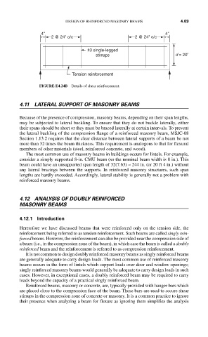
4" 4"
2 @ 24" o/c 2 @ 24" o/c
#3 single-legged
stirrups d = 20"
Tension reinforcement
FIGURE E4.24B Details of shear reinforcement.
4.11 LATERAL SUPPORT OF MASONRY BEAMS
Because of the presence of compression, masonry beams, depending on their span lengths,
may be subjected to lateral buckling. To ensure that they do not buckle laterally, either
their spans should be short or they must be braced laterally at certain intervals. To prevent
the lateral buckling of the compression flange of a reinforced masonry beam, MSJC-08
Section 1.13.2 requires that the clear distance between lateral supports of a beam be not
more than 32 times the beam thickness. This requirement is analogous to that for flexural
members of other materials (steel, reinforced concrete, and wood).
The most common use of masonry beams in buildings occurs for lintels. For example,
consider a simply supported 8-in. CMU beam (so the nominal beam width is 8 in.). This
beam could have an unsupported span length of 32(7.63) ≈ 244 in. (or 20 ft 4 in.) without
any lateral bracings between the supports. In reinforced masonry structures, such span
lengths are hardly exceeded. Accordingly, lateral stability is generally not a problem with
reinforced masonry beams.
4.12 ANALYSIS OF DOUBLY REINFORCED
MASONRY BEAMS
4.12.1 Introduction
Heretofore we have discussed beams that were reinforced only on the tension side, the
reinforcement being referred to as tension reinforcement. Such beams are called singly rein-
forced beams. However, the reinforcement can also be provided near the compression side of
a beam (i.e., in the compression zone of the beam), in which case the beam is called a doubly
reinforced beam and the reinforcement is referred to as compression reinforcement.
It is not common to design doubly reinforced masonry beams as singly reinforced beams
are generally adequate to carry design loads. The most common use of reinforced masonry
beams occurs in the form of lintels which support loads over door and window openings;
singly reinforced masonry beams would generally be adequate to carry design loads in such
cases. However, in exceptional cases, a doubly reinforced beam may be required to carry
loads beyond the capacity of a practical singly reinforced beam.
Reinforced beams, masonry or concrete, are, typically provided with hanger bars which
are placed close to the compression face of the beam. These bars are used to secure shear
stirrups in the compression zone of concrete or masonry. It is a common practice to ignore
their presence when analyzing a beam for flexure as ignoring them simplifies the analysis