
Page 347 - Design of Reinforced Masonry Structures
P. 347
COLUMNS 5.67
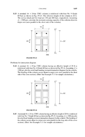
5.13 A nominal 16- × 24-in. CMU column is reinforced with four No. 9 Grade
60 bars as shown in Fig. P5.13. The effective height of the column is 20 ft.
The service dead and live load are 150 and 200 kips, respectively. Assuming
′ f = 2500 psi, calculate the moment-carrying capacity of the column about its
m
major axis (axis parallel to the short side of the column).
5"
15
8
5"
23 h = 20'
8
4#9
FIGURE P5.13
Problems for interaction diagram
5.14 A nominal 16- × 24-in. CMU column having an effective height of 20 ft is
reinforced with four No. 6 Grade 60 bars as shown in Fig. P5.14. Assuming ′ f =
m
1500 psi, plot the axial load-bending moment interaction diagram for the column.
The bending of the column occurs about its major axis (axis parallel to the short
side of the cross section). (Hint: See Example 5.11 for sample calculations.)
5"
15
8
5"
23 h = 20'
8
4#6
FIGURE P5.14
5.15 A nominal 16- × 24-in. CMU column having an effective height of 20 ft is reinforced
with four No. 7 Grade 60 bars as shown in Fig. P5.15. Assuming ′ f = 1500 psi, plot
m
the axial load-bending moment interaction diagram for the column. The bending of
the column occurs about its minor axis (axis parallel to the long side of the cross
section). (Hint: See Example 5.11 for sample calculations.)