
Page 501 - Design of Reinforced Masonry Structures
P. 501
SHEAR WALLS 7.63
configurations as discontinuous shear wall
or frames (in a building elevation), uneven
distribution of mass on various levels of
Center of a building, and significant differences in
mass story stiffnesses (See Figs. 7.24–7.26).
For design purposes, five types of verti-
cal structural irregularities are recognized
(ASCE 7-05 Section 12.3.2.2) as listed in
Table 7.7.
Center of
rigidity
1. (a) Stiffness-soft story irregularity, (b)
stiffness-extreme soft story irregularity
2. Weight (mass) irregularity
3. Vertical geometric irregularity
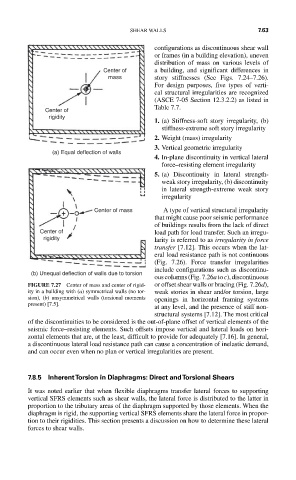
(a) Equal deflection of walls
4. In-plane discontinuity in vertical lateral
force–resisting element irregularity
5. (a) Discontinuity in lateral strength-
weak story irregularity, (b) discontinuity
in lateral strength-extreme weak story
irregularity
Center of mass A type of vertical structural irregularity
that might cause poor seismic performance
of buildings results from the lack of direct
Center of load path for load transfer. Such an irregu-
rigidity larity is referred to as irregularity in force
transfer [7.12]. This occurs when the lat-
eral load resistance path is not continuous
(Fig. 7.26). Force transfer irregularities
include configurations such as discontinu-
(b) Unequal deflection of walls due to torsion
ous columns (Fig. 7.26a to c), discontinuous
FIGURE 7.27 Center of mass and center of rigid- or offset shear walls or bracing (Fig. 7.26d),
ity in a building with (a) symmetrical walls (no tor- weak stories in shear and/or torsion, large
sion), (b) unsymmetrical walls (torsional moments openings in horizontal framing systems
present) [7.5].
at any level, and the presence of stiff non-
structural systems [7.12]. The most critical
of the discontinuities to be considered is the out-of-plane offset of vertical elements of the
seismic force–resisting elements. Such offsets impose vertical and lateral loads on hori-
zontal elements that are, at the least, difficult to provide for adequately [7.16]. In general,
a discontinuous lateral load resistance path can cause a concentration of inelastic demand,
and can occur even when no plan or vertical irregularities are present.
7.8.5 Inherent Torsion in Diaphragms: Direct and Torsional Shears
It was noted earlier that when flexible diaphragms transfer lateral forces to supporting
vertical SFRS elements such as shear walls, the lateral force is distributed to the latter in
proportion to the tributary areas of the diaphragm supported by those elements. When the
diaphragm is rigid, the supporting vertical SFRS elements share the lateral force in propor-
tion to their rigidities. This section presents a discussion on how to determine these lateral
forces to shear walls.