Page 504 - Design of Reinforced Masonry Structures
P. 504
7.66                      CHAPTER SEVEN

         3. The eccentricities in the structural stiffness due to nonstructural elements such as stairs
           and interior partitions
         4. Torsional input loading on the structure due to differences in seismic ground motion
           over the extent of foundation

           Accidental torsional moment is a force that is assumed to act in addition to the torsional
         moment due to actual eccentricity (inherent torsion). Thus, total torsional moment acting
         on the system would be equal to torsional moment given by Eq. (7.72):

                                     V(e ± e )                       (7.72)
                                          acc
         where  V = lateral seismic force
               e = eccentricity
             e  = accidental eccentricity
              acc
                = ± 5 percent of structure dimension perpendicular to the applied seismic force.

           The minus sign in Eq. (7.72) should be used when the torsional shear would act to
         reduce the effects of direct shear; plus sign should be used when the torsional shear would
         act in the same direction as the direct shear. In some cases of analyses, the seismic forces
         may be applied in two orthogonal directions concurrently. In such cases, it is not necessary
         to apply the required 5 percent displacement of the center of mass in both of the orthogonal
         directions concurrently. However, this 5 percent required displacement must be applied in
         the direction that causes more critical effect.


         7.8.7 Amplification of Accidental Torsional Moments
         When structures assigned to seismic design categories C, D, E, and F have horizontal
         structural irregularity Type 1a or 1b listed in Table 7.6, the effects of accidental torsional
         eccentricity are required to be accounted for by multiplying M  by a torsional amplification
                                                     ta
         factor given by Eq. (7.73):

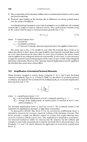
                                       ⎛ δ   ⎞  2
                                   A =  ⎜  max  ⎟                    (7.73)
                                    x
                                       ⎝ .12 δ avg  ⎠
         where  A  = amplification factor ≤ 3.0
                x
             d max  = the maximum displacement at level x computed assuming A  = 1
                                                             x
              d  =  average of the displacements at extreme points of structure at level x com-
              avg

                  puted assuming A  = 1
                               x
         The torsional amplification factor  A  need not exceed 3. The accidental torsion is not
                                   x
         required to be amplified for structures of light frame construction.
           As discussed in SEAOC Blue Book [7.12], the eccentricity amplification factor is
         intended to represent the increases caused by yielding of the perimeter elements. This
         factor provides a simple yet effective control on systems that might otherwise have
         excessive torsional yield in a given story. This requirement is intended to avoid poten-
         tial torsional mechanism failure by ensuring that the structure has the stiffness and
         strength to resist both calculated and accidental torsional effects (discussed later). See
         Examples 7.13 and 7.14 which illustrate the application of eccentricity amplification
         factor, A .
               x

