
Page 507 - Design of Reinforced Masonry Structures
P. 507
SHEAR WALLS 7.69
3. Structures assigned to certain seismic design categories and having certain types of
structural irregularities are not permitted to be built:
(a) Structures assigned to Seismic Design Category D and having vertical structural
irregularity Type 5b are not permitted to be built.
(b) Structures assigned to seismic design categories E and F and having horizontal
structural irregularity Type 1b or vertical structural irregularity Type 1b, 5a, or 5b are
not permitted to be built.
7.9 ANALYSIS OF SHEAR WALLS AND
DIAPHRAGMS UNDER DIRECT SHEAR
AND TORSIONAL MOMENTS
When a rigid diaphragm transmits a seismic force to two parallel shear walls of equal rigidi-
ties and the center of mass is coincident with the center of rigidity, the seismic force would
be transmitted equally to both shear walls. But when the center of mass is not coincident with
the center of rigidity, which happens when the shear wall have unequal rigidities, a torsional
moment would be caused that must be resisted by shear walls. In such a case, forces in shear
wall can be determined from superposition of two cases: (a) direct shear, (b) torsional shear.
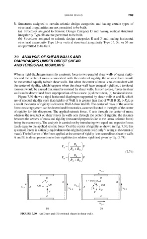
Figure 7.30 shows a rigid horizontal diaphragm supported by shear walls A and B, which
are of unequal rigidity such that rigidity of Wall A is greater than that of Wall B (R > R ); as
A B
a result the center of rigidity is closer to Wall A than Wall B. The center of mass of the seismic
force–resisting system can be determined from statics, assumed located to the right of the center
of rigidity for this discussion. The applied seismic force, V, acts through the center of mass,
whereas the resultant of shear forces in walls acts through the center of rigidity, the distance
between the centers of mass and rigidity (measured perpendicular to the lateral seismic force)
being the eccentricity. The analysis is carried out by introducing two equal and opposite forces
(each equal to the applied seismic force V) at the center of rigidity as shown in Fig. 7.30; this
system of forces is statically equivalent to the original system (with only V acting at the center of
mass). The influence of the force applied at the center of rigidity is to cause direct shear in walls
A and B, in direct proportion to their rigidities (or relative rigidities) given by Eq. (7.74):
⎛ R ⎞
V = A V
A ⎜ ⎝ R + R ⎠ ⎟
A B (7.74)
⎛ R ⎞
V = ⎜ B ⎟ V
B ⎝ R + R ⎠
A
B
V T, D
D D
e T = V(e ± e acc )
B V B
CM CM
A CR + + V T, A A ++
V D,A
V D, B CR V T, B
V
V V
C C
V T, C
(a) (b)
FIGURE 7.30 (a) Direct and (b) torsional shears in shear walls.