
Page 512 - Design of Reinforced Masonry Structures
P. 512
7.74 CHAPTER SEVEN
Example 7.13 Distribution of lateral forces from a rigid diaphragm to
shear walls involving horizontal structural irregularity (torsional irregular-
ity Type 1a).
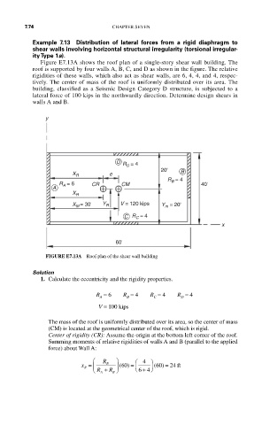
Figure E7.13A shows the roof plan of a single-story shear wall building. The
roof is supported by four walls A, B, C, and D as shown in the figure. The relative
rigidities of these walls, which also act as shear walls, are 6, 4, 4, and 4, respec-
tively. The center of mass of the roof is uniformly distributed over its area. The
building, classified as a Seismic Design Category D structure, is subjected to a
lateral force of 100 kips in the northwardly direction. Determine design shears in
walls A and B.
y
D
R D = 4
20' B
e
X R
R B = 4
R = 6 CR CM 40'
A A
X R
X M = 30' Y R V = 120 kips Y m = 20'
C R C = 4
x
60'
FIGURE E7.13A Roof plan of the shear wall building
Solution
1. Calculate the eccentricity and the rigidity properties.
R = 6 R = 4 R = 4 R = 4
C
D
B
A
V = 100 kips
The mass of the roof is uniformly distributed over its area, so the center of mass
(CM) is located at the geometrical center of the roof, which is rigid.
Center of rigidity (CR): Assume the origin at the bottom left corner of the roof.
Summing moments of relative rigidities of walls A and B (parallel to the applied
force) about Wall A:
⎛ R ⎞ ⎞
x = ⎜ ⎝ R + B R ⎠ ⎟ (60 ) = ⎜ ⎛ 4 ⎟ (60 ) = 24 ft
+ ⎠
R
⎝ 64
A
B