
Page 516 - Design of Reinforced Masonry Structures
P. 516
7.78 CHAPTER SEVEN
Commentary:
1. To get an overall understanding of the influence of torsional moment, it is noted
that total lateral force that must be resisted by walls A and B equals 58.9 + 51.1 =
110 kips versus applied lateral force of 100 kips.
2. The torsional moment also introduces shear force in walls C and D, but they are
not considered in this example as these walls are perpendicular to the applied
lateral force and do not participate in resisting the applied lateral force.
Example 7.14 Distribution of lateral forces from a rigid diaphragm to
shear walls involving extreme torsional irregularity (horizontal structural
irregularity Type 1b).
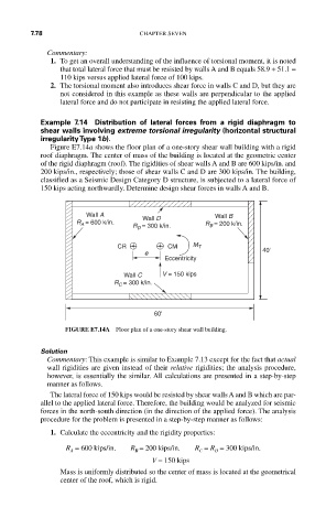
Figure E7.14a shows the floor plan of a one-story shear wall building with a rigid
roof diaphragm. The center of mass of the building is located at the geometric center
of the rigid diaphragm (roof). The rigidities of shear walls A and B are 600 kips/in. and
200 kips/in., respectively; those of shear walls C and D are 300 kips/in. The building,
classified as a Seismic Design Category D structure, is subjected to a lateral force of
150 kips acting northwardly. Determine design shear forces in walls A and B.
Wall A Wall B
R A = 600 k/in. Wall D R B = 200 k/in.
R D = 300 k/in.
CR CM M T 40'
e
Eccentricity
Wall C V = 150 kips
R C = 300 k/in.
60'
FIGURE E7.14A Floor plan of a one-story shear wall building.
Solution
Commentary: This example is similar to Example 7.13 except for the fact that actual
wall rigidities are given instead of their relative rigidities; the analysis procedure,
however, is essentially the similar. All calculations are presented in a step-by-step
manner as follows.
The lateral force of 150 kips would be resisted by shear walls A and B which are par-
allel to the applied lateral force. Therefore, the building would be analyzed for seismic
forces in the north-south direction (in the direction of the applied force). The analysis
procedure for the problem is presented in a step-by-step manner as follows:
1. Calculate the eccentricity and the rigidity properties:
R = 600 kips/in. R = 200 kips/in. R = R = 300 kips/in.
D
C
A
B
V = 150 kips
Mass is uniformly distributed so the center of mass is located at the geometrical
center of the roof, which is rigid.