Page 518 - Design of Reinforced Masonry Structures
P. 518

7.80                      CHAPTER SEVEN


                                                       V T, D
                         D                              D
                        e
                                  B             T = V(e ± e acc )  B
                          CM
                    CR                   V T, A          CM
                A      +  +                   A      + +
           V D,A
                                                    CR
                                      V D, B                         V T, B
                        V
                         C                              C
                                                       V T, C
                         (a)                            (b)
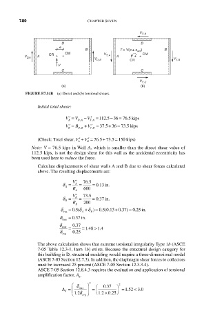
           FIGURE E7.14B  (a) Direct and (b) torsional shears.
                Initial total shear:

                                               =
                                                   .5
                                   V
                           V ′ = V  − ′ = 112 .5 − 36 76 kips
                                     ,
                                ,
                             A  D A  T A
                                               =
                                                  .5
                                          5
                                   V
                           V ′ = B  + ′ = 37 . + 36 73 kips
                                ,
                            B  D B  T TB
                                     ,
                              V
                (Check: Total shear, ′ + ′ = 76 5 73 5 150.  +  .  =  kips)
                                  V
                                A  B
             Note: V = 76.5 kips in Wall A, which is smaller than the direct shear value of
             112.5 kips, is not the design shear for this wall as the accidental eccentricity has
             been used here to reduce the force.
                Calculate displacements of shear walls A and B due to shear forces calculated
                above. The resulting displacements are:
                             V ′  76 5 .
                         δ =  A  =   = 013 in.
                                       .
                           A
                             R  A  600
                             V ′  73 5 .
                         δ =  B  =   = 0.337 in.
                           B
                             R B  200
                         δ  =         =
                                                      .
                          avg  05 δ +.(  A  δ )  05 013 037 =.( .  + . )  025 in..
                                    B
                        δ max  = 037 in.
                              .
                        δ    037
                              .
                                      >
                         max  =  = 148 14
                                        .
                                   .
                        δ    025
                              .
                         avg

                The above calculation shows that extreme torsional irregularity Type 1b (ASCE
                7-05 Table 12.3-1, Item 1b) exists. Because the structural design category for
                this building is D, structural modeling would require a three-dimensional model
                (ASCE 7-05 Section 12.7.3). In addition, the diaphragm shear forces to collectors
                must be increased 25 percent (ASCE 7-05 Section 12.3.3.4).
                ASCE 7-05 Section 12.8.4.3 requires the evaluation and application of torsional
                amplification factor, A .
                                x
                             ⎛ δ   ⎞  2  ⎛  . 037  ⎞  2
                          A = ⎜  max  ⎟  = ⎜  ⎟ = 1..52 3<  .0
                                              ⎠
                          X
                             ⎝ .12 δ avg  ⎠  ⎝ .12 × .025
   513   514   515   516   517   518   519   520   521   522   523