Page 513 - Design of Reinforced Masonry Structures
P. 513

SHEAR WALLS                       7.75

                Summing up moments of relative rigidities of walls C and D about Wall C:

                             ⎛  R   ⎞          ⎞
                          y =    D   (40 )  = ⎜ ⎛ 4  ⎟ (40 )  = 20 ft
                                            + ⎠
                          R  ⎜ ⎝  R +  R ⎠ ⎟  ⎝ 44
                                   D
                               C
                (or from symmetry, y  = ½ (40) = 20 ft)
                               R
                The center of mass is located at x  = ½(60) = 30 ft from either wall.
                                        M
                Eccentricity e = x  – x  = 30 – 24 = 6 ft
                            M
                                R
                Calculate the polar moment of inertia of shear walls, J, about the center of rigidity.
                                                2
                              2
                                         2
                      J = R  (x )  + R  (60 − x )  + R (y )  + R  (40 − y ) 2
                          A
                                       R
                            R
                                               R
                                                          R
                                                    D
                                 B
                                            C
                                       2
                                              2
                             2
                       = 6 (24)  + 4 (60 − 24)  + 4 (24)  + 4 (48 − 24) 2

                       = 11, 840 ft 2
             2.  Direct shear in walls A and B: The rigidity of the building in the direction of the
                force equals the sum of rigidities of walls parallel to the force. In this example,
                shear walls A and B are parallel, and are oriented in the direction of applied lat-
                eral force. Therefore, they would share the applied lateral force in proportion to
                their rigidities. Accordingly,
                             ⎛  R   ⎞    ⎛ 6  ⎞
                        V  =  ⎜  A  ⎟  V () = ⎜  ( ⎟ 100 ) = 60 kipss
                                           + ⎠
                         DA  ⎝  R +  R ⎠  ⎝ 64
                          ,
                                   B
                               A
                             ⎛  R   ⎞    ⎛ 4  ⎞
                        V DB  =  ⎜ ⎝  R + B R ⎠ ⎟  V () = ⎜ ⎝ 66  ( ⎟ 100 ) = 40 kips
                                                         s
                                           + ⎠
                          ,
                               A
                                   B
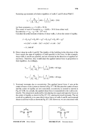
             3.  Torsional moments due to eccentricity: The applied lateral force V acts at the
                center of mass of the system as shown in Fig. E7.13B. Because the center of mass
                and the center of rigidity are not coincident, eccentricity is created as shown in
                Fig. E7.13B. As a result, the applied shear force is transmitted to the wall eccen-
                trically. This situation is analyzed by introducing two equal and opposite forces at
                the center of rigidity as shown in Fig. E7.13C causing torsional moments. The net
                result of eccentricity is to cause direct shear forces in walls A and B, and torsional
                shears in all four walls as shown in Fig. E7.13D. However, we are concerned with

                         e                             V   e
                   CR       CM                        CR      CM
                           V
                                                          V  V
             FIGURE E7.13B  Direct shears.    FIGURE E7.13C  Torsional shears.
   508   509   510   511   512   513   514   515   516   517   518