
Page 510 - Design of Reinforced Masonry Structures
P. 510
7.72 CHAPTER SEVEN
of applied lateral force. Therefore, they would share the applied lateral force in
proportion to their relative rigidities.
⎛ R ⎞ ⎛ . 45 ⎞
=
)
V = ⎜ A ⎟ V () = ⎜ ( ⎟ 100 = 45 kips
,
DA ⎝ R + R ⎠ ⎝ 45 . ⎠
. + 55
A B
⎛ R ⎞ ⎛ . 55 ⎞
=
V = ⎜ B ⎟ V () = ⎜ ( ⎟ 100 = 55 kips
)
,
DB ⎝ R + R ⎠ ⎝ 45 . ⎠
. + 55
A B
3. Plan irregularity considerations: The influence of torsional irregularity needs to
be determined as specified in Table 12.3-1 (ASCE 7-05). It requires determina-
tion of story drifts in walls A and B. This evaluation must include accidental
torsion caused by an eccentricity of 5 percent of the building dimension perpen-
dicular to the applied force each way (ASCE 7-05, Section 12.8.4.2), 90 ft in this
example.
Additional eccentricity ± e = 0.05 (90) = 4.5 ft
acc
Total eccentricity e total = (4.5 ± 4.5) ft
Initial torsional shear: Calculate from Eq. (7.75).
M = Ve acc
ta
Based on V = 100 kips, and e = (4.5 + 4.5) ft
+ . )(49 5
A
acc
R
V ′ = Ve ( + e )( x )( R ) = 100 (. 4 5 4 5 . )((. )45 = . 736 kips
TA
,
J 27 ,248
Ve )(60 − x )(R ) (100 ) . +4 5 4 5 − . )( . )
( + e
(
. (90 49 5 5 5
V ′ = acc R B = = . 7366kips
, TB
J 27 ,248
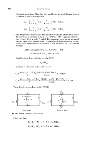
These shear forces are shown in Fig. E7.12B.
T
V D
D
D
V = 100 kips V
B M T B
A CM CM A CM
C V D 1 B V C V
T
T
V D 1 A V V A CR V B
T
V C
Direct shears Torsional shears
FIGURE E7.12B Direct and torsional shears.
Initial total shear:
=
.
V
V A ′ = V D A − ′ = 45 + .736 5236 kips
,
T A
,
−
=
.
V B ′ = V D B + ′ = 55 736 4764kips
V
.
,
,
T TB