
Page 509 - Design of Reinforced Masonry Structures
P. 509
SHEAR WALLS 7.71
y
D
R D = 4
A R A = 4.5
V = 100 kips
R B = 5.5 B
CM CR
60'
X M
Y m
X R
Y R
R C = 4
x
C
90'
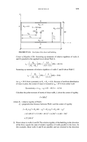
FIGURE E7.12A Roof plan of the shear wall building.
Center of Rigidity (CR): Summing up moments of relative rigidities of walls A
and B (parallel to the applied force) about Wall A:
⎛ R ⎞ ⎛ . 55 ⎞
x = B (90 ) = ⎜ ⎟ (90 ) = 4995.ft
R ⎜ ⎝ R + R ⎠ ⎟ ⎝ . 45 + . 55 ⎠
A B
Summing up moments of relative rigidities of walls C and D about Wall C:
⎛ R ⎞ ⎞
y = D (90 ) = ⎜ ⎛ 4 ⎟ (60 ) = 30 ft
+ ⎠
R ⎜ ⎝ R + R ⎠ ⎟ ⎝ 44
C D
(or y = 30 ft from symmetry as R = R = 4.0). Because of uniform distribution
R
C
D
of mass in plan, the center of mass is located at x = 45 ft from either wall.
M
Eccentricity e = x − x = 45 − 49.5 = − 4.5 ft
M
R
Calculate the polar moment of inertia of shear walls, J, about the center of rigidity.
2
J = ΣRd
i i
where R = relative rigidity of Wall i
i
d = perpendicular distance between Wall i and the center of rigidity
i
2
2
2
J = R (x ) + R (60 − x ) + R (y ) + R (40 − y ) 2
A
D
R
R
R
B
C
R
2
2
2
= 4.5 (49.5) + 5.5 (90 − 49.5) + 4 (30) + 4 (60 − 30) 2
= 27,248 ft 2
2. Direct shear in walls A and B: The relative rigidity of the building in the direction
of the force equals the sum of relative rigidities of walls parallel to the force. In
this example, shear walls A and B are parallel, and are oriented in the direction