
Page 96 - Design of Reinforced Masonry Structures
P. 96
2.48 CHAPTER TWO
consideration of stress in glass unit masonry, its compressive strength is not specified. The
compressive strength, however, may vary between 400 and 800 psi [2.7].
Presently, no ASTM or any other type of material standard is available for glass units,
and users depend on manufacturers’ data, recommendations, and construction details.
Glass units are typically square, and produced in nominal 6, 8, and 12 in. sizes, although
rectangular units are also available. Actual sizes are ⁄ 4 in. smaller, to allow for typical
1
7
1 ⁄ 4-in. mortar joints. Unit thicknesses are either “standard” that are at least 3 ⁄ 8 in. wide, or
“thin” that are 3 ⁄ 4 and 3 in. wide, respectively, for hollow and solid units (MSJC Code-08
1
Ref. [2.3], Section 7.1.3). Glass units are required to be laid in Type S or N mortar. For
exterior applications, integral water repellents can be incorporated into the mortar to help
prevent water penetration. Glass unit masonry is typically constructed in stack bond. Edges
of glass units are shaped to provide a mechanical key with the mortar, so full mortar beds
should always be used to provide maximum bond between units and mortar. To preclude
possibility of breakage or damage to units during installation, wood or rubber tools, rather
than steel, should be used to tap units into the place.
Panel sizes for glass masonry units and other requirements are specified in building
codes. They are, however, prescriptive in nature. They govern panel size, panel support,
expansion joints, mortar, and joint requirements. The panel size limitations are based on
structural and performance considerations. Height limits are more restrictive than length
limits. The panel size requirements are based on history of successful performance, testing
by independent laboratories, and manufacturers’ recommendations, rather than on engi-
neering principles or actual field experience.
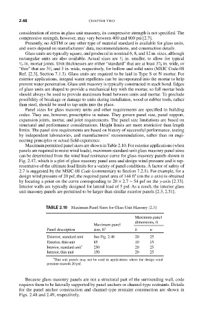
Maximum permitted panel sizes are shown in Table 2.10. For exterior applications (when
panels are required to resist wind loads), maximum standard-unit glass masonry panel sizes
can be determined from the wind load resistance curve for glass masonry panels shown in
Fig. 2.47, which is a plot of glass masonry panel area and design wind pressure and is rep-
resentative of the ultimate load limits for a variety of panel conditions. A factor of safety of
2.7 is suggested by the MSJC-08 Code (commentary to Section 7.2.1). For example, for a
2
design wind pressure of 20 psf, the required panel area of 144 ft (on the x-axis) is obtained
by locating a point on the curve corresponding to 20 × 2.7 = 54 psf on the y-axis [2.33].
Interior walls are typically designed for lateral load of 5 psf. As a result, the interior glass
unit masonry panels are permitted to be larger than similar exterior panels [2.3, 2.51].
TABLE 2.10 Maximum Panel Sizes for Glass Unit Masonry [2.3]
Maximum panel
dimensions, ft
Maximum panel
Panel description size, ft 2 h w
Exterior, standard unit See Fig. 2.48 20 25
Exterior, thin unit 85 10 15
Interior, standard unit * 250 20 25
Interior, thin unit 150 20 25
* Thin unit panels may not be used in applications where the design wind
pressure exceeds 20 psf.
Because glass masonry panels are not a structural part of the surrounding wall, code
requires them to be laterally supported by panel anchors or channel-type restraints. Details
for the panel anchor construction and channel-type restraint construction are shown in
Figs. 2.48 and 2.49, respectively.