
Page 306 - Design of Simple and Robust Process Plants
P. 306
292 Chapter 8 Instrumentation, Automation of Operation and Control
8.2.4
Safety Instrument Systems (SIS)
The design of safety instrument systems (SIS) is a way of improving the protection
of process plants, and this approach has found a much wider application. The pro-
tection of an ammonia pressure storage tank was shown in Figure 3.5 in Chapter 3,
where the design was simplified by the installation of SIS. Other, similar situations
also exist, such as the early detection of a runaway reaction, where a SIS can protect
the process by timely adequate instrumental actions. These situations are more diffi-
cult to handle by conventional hardware safety relief devices. At the moment, pres-
sure relief devices detect the extent of the runaway reaction at such a point that large
quantities of chemicals have to be released. These amount are difficult to recover,
and might cause high environmental loads. Furnaces are also provided with burner
management systems for protection against uncontrolled reactions such as explo-
sions. The design and maintenance of these SIS are prescribed in IEC 61508, this
approach being referred to as the ªLife Cycle Safetyº. The SIS need to operate over
the process lifetimes, and therefore include maintenance and inspection activities to
keep the SIS up to date.
The first step of the quantitative methodology in the design of SIS systems con-
sists of determination of the safety integrity level (SIL). The SIL is a measure for the
risk of a process, the risk being impacted by the likelihood of the event, and the
consequences. The consequences are divided into three terms: personal safety;
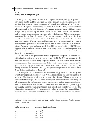
production and equipment loss; and environment. In IEC 61508, the average prob-
ability of failure on demand (PFD AVG ) for protective systems of low demand has
been defined and is given in Table 8.3.
The design of the SIS must meet the criteria of the applicable SIL. The design is a
quantitative approach where not only PFD AVG is calculated but also the number of
expected false (nuisance) trips must be quantified. Several SIS configurations are
evaluated at that stage. The SIS must be analyzed for reliability and availability for
all components in the loop from sensor, transmitters, wiring, instrumentation sys-
tem hardware as well as software, actuators as switch, final element, power supply,
air supply, response time, maintenance and operational procedures. For the SIS
alternatives, quantitative fault trees are developed to determine the average PFD and
nuisance trips. A common mode failure needs to be part of the analysis. The optimal
Table 8.3. Safety integrity level and the average probability of failure on demand for a low-demand
situation (IEC 61508).
Safety integrity level Average probability on demand
±5
4 10 <10 ±4
±4
3 10 <10 ±3
±3
2 10 <10 ±2
±2
1 10 <10 ±1