
Page 356 - Design of Simple and Robust Process Plants
P. 356
342 Chapter 8 Instrumentation, Automation of Operation and Control
its constraints, and its predictions. Despite these limitations, they have found wide
acceptance for predictive and constraint control, and have obtained a solid position
in the operational pyramid (see Figure 8.1).
The above does not limit the model-based control layer from performing some
elementary calculations to support control, without compromising on robustness.
Model-based control at the basic control layer must be restricted in order to
achieve the required level of robustness. These restrictions within the current state
of the technology are:
. Apply algebraic equations which make solving a straightforward exercise.
. Avoid optimization and iterations ± a straightforward answer is not guaran-
teed.
. Avoid constraint control ± constraints are always difficult to model.
. Avoid predictive action, as these introduce a level of uncertainty
The models are preferably derived from fundamental models, including mass and
energy balances which have a wide application area.
With the above restrictions in mind, there are still many opportunities for applica-
tions. The applications of ratio controller or feed-forward controller provided with
corrections for response times are the most elementary. The design of a controller
based on heat balances (as applied in Figure 4.29 in Chapter 4) is a simple example.
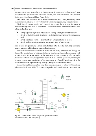
A more pronounced application of the development of model-based control at the
basic control layer is published by Verwijs (2001) and is described below.
An exothermal hydrogenation plug flow reactor designed as a tray bubble column
(illustrated in Figure 8.18). The reaction is performed in a slurry type co-current, up-
P
Vapor
Product
T
L
T F
Solvent
T
F F T
T
F
F
L
F
T
Reactants
Fig. 8.18. Initial reactor control design with operators to control
six interactive loops (Ref. Verwijs '01).