
Page 36 - Design of Simple and Robust Process Plants
P. 36
1.11 Overall Example of Process Design 19
is the opening of the reactor, which brings operators into direct contact with chemi-
cals and introduces air into the reactor vessel ± a situation which is often undesir-
able. The size of the reactor was limited due to fabrication limits and the limited
cooling capacity for jacketed vessels. A larger vessel diameter increases the volume
with the cube of the diameter, while the surface area increases with the square of
the diameter.
The second generation of this batch process is shown in Figure 1.5. The reactor is
provided with continuous feed streams to establish a more constant heat generation
during the reaction feed step. To accommodate this, feed vessels are installed in
front of the reactor vessel. Opening of the reactor vessel is avoided by adding the
ingredients into harmless feed systems, or separate dosing systems are installed to
supply the additives. Following the reactor in this example, a post reactor is applied,
and de-volatilizing and cooling is carried out in separate vessels. The product is
intermediately stored in lot tanks to equalize the product, followed by storage. The
flowsheet represents a large increase in capacity by providing additional equipment
where the feed preparation and treatment steps are carried out, while the process is
automated. The additional equipment was in general justified based on incremental
economics. The reactor vessel was reserved for the reaction alone. Larger reactor
vessels could be applied (which by that time could be fabricated) due to the
improved control of the heat generation. Two reactor systems are shown to cover the
increased demand.
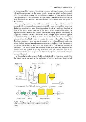
In the third-generation process, feed is applied directly to the reactor vessel, while
the reactor size is increased by the application of a reflux condenser, though it still
Condensor Vent condensor
Water
Additives Vent
recovery
~~~~~~~~~~~~~~
H.C. 1 feed cooling/
heating
H.C. 2 feed
Feed / Dosing Tanks Con-Add batch reactor Post reactor Devolatization Cooling
Floating storage Additives Basic product tanks Filter
Fig. 1.6. Third-generation flowsheet of continuously added
batch reactor system with refluxing condensor and floating
storage.