
Page 139 - Designing Autonomous Mobile Robots : Inside the Mindo f an Intellegent Machine
P. 139
Chapter 8
X
Y
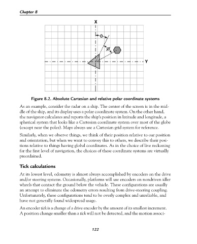
Figure 8.2. Absolute Cartesian and relative polar coordinate systems
As an example, consider the radar on a ship. The center of the screen is in the mid-
dle of the ship, and its display uses a polar coordinate system. On the other hand,
the navigator calculates and reports the ship’s position in latitude and longitude, a
spherical system that looks like a Cartesian coordinate system over most of the globe
(except near the poles). Maps always use a Cartesian grid system for reference.
Similarly, when we observe things, we think of their position relative to our position
and orientation, but when we want to convey this to others, we describe their posi-
tions relative to things having global coordinates. As in the choice of live reckoning
for the first level of navigation, the choices of these coordinate systems are virtually
preordained.
Tick calculations
At its lowest level, odometry is almost always accomplished by encoders on the drive
and/or steering systems. Occasionally, platforms will use encoders on nondriven idler
wheels that contact the ground below the vehicle. These configurations are usually
an attempt to eliminate the odometry errors resulting from drive-steering coupling.
Unfortunately, these configurations tend to be overly complex and unreliable, and
have not generally found widespread usage.
An encoder tick is a change of a drive encoder by the amount of its smallest increment.
A position change smaller than a tick will not be detected, and the motion associ-
122