
Page 140 - Designing Autonomous Mobile Robots : Inside the Mindo f an Intellegent Machine
P. 140
Live Reckoning
ated with a tick will normally be approximated as a straight tick vector to be added to
the platform’s position estimate. The higher the resolution of an encoder, the smal-
ler the errors produced by these approximations will be.
Encoders are usually binary in nature, so their resolutions can be any power of two.
Typical resolutions range from 32 to 4096. Signals associated with the act of driving
generally cause a tick interrupt to the navigation computer. Thus, for drive encoders,
the important issue is the amount of travel represented by a single tick. If the tick
distance is made too large, the odometry calculation will be inaccurate because it will
be incapable of tracking fluctuations in the vehicle’s course during the tick interval.
On the other hand, if the resolution is needlessly small, the encoder will cause an
excessive overhead for the computer it is interrupting. As a rule of thumb, the tick
distance should be about one thousandth of the distance between the wheels or
treads of the vehicle.
For those systems with steering encoders, the angle of the tick vector will be trun-
cated (not rounded) to the resolution of the encoder. It is highly desirable that the
steering encoder be mounted as close to the steered wheel(s) as possible, so that it is
not affected by the mechanical backlash of the steering mechanism. The resolution
of the steering encoder should be about a factor of three smaller than the backlash
between it and the actual wheels. Typical resolutions will range from 1024 and up.
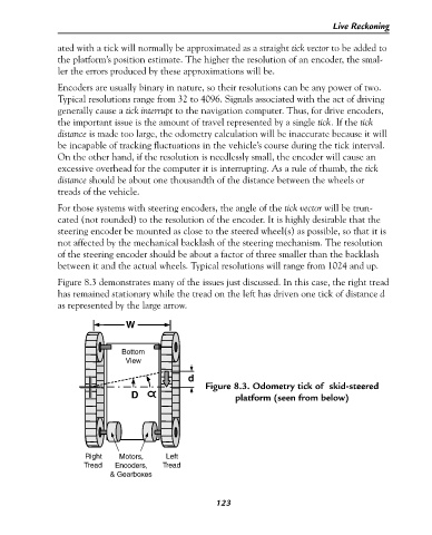
Figure 8.3 demonstrates many of the issues just discussed. In this case, the right tread
has remained stationary while the tread on the left has driven one tick of distance d
as represented by the large arrow.
W
Bottom
View
d
Figure 8.3. Odometry tick of skid-steered
D platform (seen from below)
Right Motors, Left
Tread Encoders, Tread
& Gearboxes
123