
Page 23 - Designing Autonomous Mobile Robots : Inside the Mindo f an Intellegent Machine
P. 23
Chapter 1
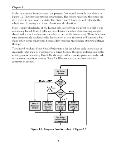
Coded as a simple linear program, the program flow would resemble that shown in
Figure 1.2. The first task gets the sonar ranges. The robot’s mode and the ranges are
then tested to determine the state. The State 3 and 4 functions will calculate the
robot’s rate of turning, and its acceleration or deceleration.
State 1 simply decelerates at the highest safe rate to bring the robot to a halt if it is
not already halted. State 2 (all clear) accelerates the robot while steering straight
ahead, and states 3 and 4 cause the robot to turn while decelerating. These functions
must continuously recalculate the deceleration so that the robot will come to a halt
if and when either sonar range becomes less than the programmed stopping distance
(Dstop).
The desired result for State 3 and 4 behaviors is for the robot’s path to arc at an in-
creasingly tight angle as it approaches a target because the speed is decreasing as the
steering rate is increasing. Hopefully, the target will eventually pass away to the side
of the sonar transducer pattern, State 2 will become active, and our robot will
continue on its way.
Get Sonar
Ranges
Mode = OFF Mode
Test
L > D max
and
R > D R < L
max Range
Test
L < R
State 2 State3 State 4
State 1
Decelerate Accelerate Decelerate Decelerate
and Turn
Straight
and Turn
to Halt
Ahead Right Left
Run Motors
and do other
Housekeeping
Figure 1.2. Program flow for robot of Figure 1.1
6