
Page 325 - Distillation theory
P. 325
P1: JPJ/FFX P2: FCH/FFX QC: FCH/FFX T1: FCH
0521820928c08 CB644-Petlyuk-v1 June 11, 2004 20:20
8.4 Multicomponent Azeotropic Mixtures: Presynthesis 299
a) 1 b) 1 c) 2
x t 2− 4−
x t 5
2− 4− 3
15 15
3 5 3 5 3 5
x D
t 24
x 1− 2− x t
3
x D t x D 1− 4− 5
x 1− 2− 5 x 1− t 4− 3
2 4 4
d) 2
24
1 4
3,5
(3)
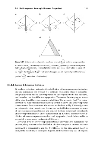
Figure 8.19. Determination of possible overhead product Reg D on three-component face
1,2,4
1-2-4ofthewater(1)-methanol(2)-aceticacid(3)-acetone(4)-pyridine(5)concentrationpenta-
hedron. Segments of possible overhead product (triple line) on the binary edges of face 1-2-4:
3,5 3,5 3,5
(2) (2) (2)
(a) Reg , (b) Reg , (c) Reg D = [2-4] (whole edge), and (d) region of possible overhead
D
D
1,2 1,4 2,4
3,5
(3)
product Reg D on the face 1-2-4(hatched).
1,2,4
8.4.6.4. Example 2: Extractive distillation
To analyze variants of autoextractive distillation with one-component entrainer
and one-component top product, it is sufficient to examine edges of concentra-
tion pentahedron: one of the components of the edge should be the entrainer,
and the other one should be the top product. The rest of the components absent
t(2)
at the edge should have intermediate volatilities. The segments Reg e of trajec-
tory tear-off of intermediate section at separation of three- and four-component
constituents of five-component mixture are marked out in Fig. 8.20 at edges that
do not contain binary azeotropes. As one can see in this figure, one can separate
all three-component constituents and some of the four-component constituents
of five-component mixture under consideration by means of autoextractive dis-
tillation with one-component entrainer and top product, but it is impossible to
separate five-component mixtures itself this way.
However, if we use a two-component entrainer or obtain a two-component top
product, sharp autoextractive distillation of a five-component mixture becomes
ijk
possible. It is convenient to use Fig. 8.13 (Reg ord in two-dimensional faces) to
analyze the possibility of such splits. Figure 8.21 shows trajectory tear-off regions