
Page 53 - Drilling Technology in Nontechnical Language
P. 53
44 Drilling Technology in Nontechnical Language Second Edition
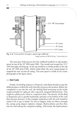
Fig. 3–6. Cross section through a spool-type wellhead
Image courtesy of GE Oil & Gas, © Vetco Gray, Inc.
The next part of the process for this wellhead would be to add another
spool on top of the 20" (508 mm) CHH. This would seal around the 13⅜"
(340 mm) pipe sticking up. At the top would be a similar profile to the top
of the 20" (508 mm) CHH, which would allow the next casing hanger to
suspend the next section of casing. This next spool is visible in the center
photograph in the figure above.
Well uids
Finally, the drilling engineer will specify what fluids should occupy the
different spaces within the well when the rig leaves the location. Before the
completion is run into the well, the drilling fluid remaining on the inside
would normally be replaced with a specially designed filtered brine. This
might be called packer fl uid or completion fl uid. The density of this fluid
is designed to give a greater hydrostatic pressure at the bottom of the well
than the pore pressure. In the example exploration well, the well would be
tested if oil or gas is found. For this to happen, holes are blown through
the casing using shaped explosive charges. Hydrocarbons can then flow
into the well and up the completion tubing. Afterwards, the hydrocarbons
_Devereux_Book.indb 44 1/16/12 2:06 PM