
Page 224 - Dust Explosions in the Process Industries
P. 224
196 Dust Explosions in the Process Industries
STORE
ROOM
I
- COVERED
WALK-WAYS
ROOM
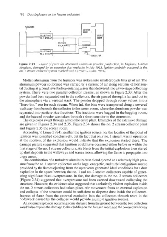
Figure 2.33 Layout of plant for atomized aluminum powder production, in Anglesey, United
Kingdom, damaged by an extensive dust explosion in July 1983. Ignition probably occurred in the
no. 1 stream collector system marked with * (From C. Lunn, 1984).
Molten aluminum from the furnaces was broken into small droplets by ajet of air. The
aluminum powder so formed was carried by a current of air along sections of horizon-
tal ducting at ground level before entering a riser that deliveredit to a two-stagecollecting
system. There were two parallel collector streams, as shown in Figure 2.33. After the
powder had been separated out in the collectors, the airpassed through a fan and out to
the atmosphere via a vertical stack. The powder dropped through rotary valves into a
“Euro-bin,” one for each stream. When full, the bins were transported along a covered
walkway from beneath the collector to the screen room, where the aluminumpowder was
separated into particle-size fractions. The fractions were bagged in the bagging room,
and the bagged powder was taken through a short corridor to the storeroom.
The explosion swept through almost the entire plant. Examples of the extensivedamage
are given in Figures 2.34 and 2.35. Figure 2.34 shows the no. 2 stream collector plant
and Figure 2.35 the screen room.
According to Lunn (1984), neither the ignition source nor the location of the point of
ignition was identified conclusively,but the fact that only no. 1 stream was in operation
at the moment of the explosion would indicate that the explosion started there. The
damage picture suggested that ignition could have occurred either before or within the
first stage of the no. 1stream collectors.Air blasts from the initialexplosions then stirred
up dust deposits in the walkways and screen room, allowing the flame to propagate into
these areas.
The combination of a turbulent aluminum dust cloud ejected at a relatively high pres-
sure from the no. 1stream collectorsand a large, energetic, and turbulent ignition source
provided by the flames ejecting from the open vents generated ideal conditions for a dust
explosion in the space between the no. 1 and no. 2 stream collectors capable of gener-
ating significant blast overpressure. In fact, the damage to the no. 2 stream collectors
(Figure 2.34) suggested that overpressure had been exerted downward, collapsing the
structure. However,the evidence also suggestedthat a relatively violent explosion inside
the no. 2 stream collectors had taken place. Air movement from an external explosion
and collapse of the structure could be sufficient to disperse dust inside the collectors.
Ingress of flame from the external explosion into the collectors through tears in the
bodywork caused by the collapse would provide multiple ignition sources.
An external explosionoccurring somedistance from the ground between the two collectors
would also explainthe damageto the cladding on the furnace room and the covered walkway