
Page 374 - Dust Explosions in the Process Industries
P. 374
Propagation of Flames in Dust Clouds 343
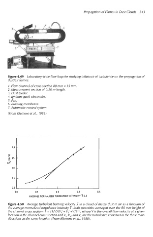
Figure 4.49 Laboratory-scale flow loop for studying influence of turbulence on the propagation of
dudair flames:
1. Flow channel of cross section 80 mm x 35 mm.
2. Measurement section of 0.50 m length.
3, Dust feeder.
4. Ignition spark electrodes.
5. Fan.
6. Bursting membrane.
7. Automatic control system.
(From Klemens et al., 1988).
2.0 -
-
- -
VI
2 1.5
IV=
1.0 -
0.5 -
0.0 I I I
0.0 0.1 0.2 0.3 0.4
AVERAGE NORMALIZED TURBULENCE INTENSITY T I-]
Figure 4.50 Average turbulent burning velocity 7 in a cloud of maize dust in air as a function of
the average normalized turbulence intensity T, both quantities averaged over the 80 mm height of
the channel cross section: T = (l/V)(Vi + V; +Vf) 'I2, where Vis the overall flow velocity at a given
location in the channel cross section and V,, Vy, and V, are the turbulence velocities in the three main
directions at the same location (From Klemens et al., 1988).