
Page 378 - Dust Explosions in the Process Industries
P. 378
Propagation of Flames in Dust Clouds 347
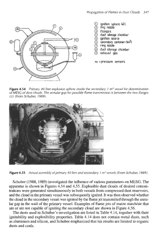
0 ignition sphere 401
@ ring nozzle
0 flanges
0 dust storage chamber
@ ignition some
0 secondary antaiir(lm3)
0 ring nozzle
0 dust storage chamber
0 exhaust gas
PR =pressure sensors
Figure 4.54 Primary 40 liter explosion sphere inside the secondary 1 m3 vessel for determination
of MESG of dust clouds. The annular gap for possible flame transmission is between the two flanges
(3) (From Schuber, 1989).
Figure 4.55 Actual assembly ofprimary 40 liter and secondary 1 m3 vessels (From Schuber, 1989).
Schuber (1988,1989) investigated the influence of various parameters on MESG. The
appgatus is shown in Figures 4.54 and 4.55. Explosible dust clouds of desired concen-
trations were generated simultaneously in both vessels from compressed dust reservoirs,
and the cloud in the primary vessel was subsequently ignited. It was then observed whether
the cloud in the secondary vessel was ignited by the flame jet transmitted through the annu-
lar gap in the wall of the primary vessel. Examples of flame jets of maize starcwair that
are or are not capable of igniting the secondary cloud are shown in Figure 4.56.
The dusts used in Schuber’s investigation are listed in Table 4.14, together with their
ignitability and explosibility properties. Table 4.14 does not contain metal dusts, such
as aluminum and silicon, and Schuber emphasized that his results are limited to organic
dusts and coals.