
Page 390 - Dust Explosions in the Process Industries
P. 390
Propagation of Flames in Dust Clouds 359
Numerous results were produced for various configurations and locations of the ignition
point. Generally, the trends found can be understood on a qualitative basis in terms of
increasingturbulence,dust entrainment,combustionrate, and venting, with increasing flow
rate in the system. However, the complex pattern of results reemphasizes the need for a
unified theoretical dust explosion model suitable for computer simulation of the course of
explosions in complex,integratedsystems for whch specific experimental data do not exist.
Pineau and Ronchail(l982) found that powders having K,, > 200 bar m/s (International
Standards Organization, 1985) can generate detonations in tubes of diameters 25-100
mm and up to 40 m length. Such detonations are associated with maximum pressures of
more than 20 bar(g) and flame speeds of about 2000 ds. This, for example, occurred
with wood dust in a 25 m long tube of 100 mm diameter, connected to a 1m3 vessel in
which the explosion was initiated. The inclusion of a 90" bend 6 m from the vessel, that
is, 19 m from the open tube exit, reduced the explosion violence somewhat, but deto-
nation still resulted in one experiment in a series of eight.
Radandt (1989) emphasized that, in industrial practice, as in dust extraction and pneu-
matic conveying systems, the initial dust clouds in ducts or tubes are not stagnant but
flow at a considerable velocity, typically in the range 15-25 ds. He therefore conducted
a comprehensive series of dust explosion experiments with a maize starch of K,, = 220
bar ds conveyed at various concentrations and velocities, using the experimental loop
illustrated in Figure 4.66.
21 m
JBEND/
U ' E J l d ! '! *# I.-..-
J
FAN
15 rn
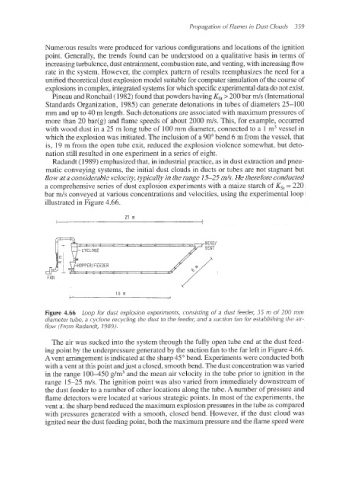
Figure 4.66 Loop for dust explosion experiments, consisting of a dust feeder, 35 m of 200 mm
diameter tube, a cyclone recycling the dust to the feeder, and a suction fan for establishing the air-
flow (From Radandt, 1989).
The air was sucked into the system through the fully open tube end at the dust feed-
ing point by the underpressure generated by the suction fan to the far left in Figure 4.66.
A vent arrangement is indicated at the sharp 45" bend. Experiments were conducted both
with a vent at this point andjust a closed, smooth bend. The dust concentration was varied
in the range 100-450 g/m3 and the mean air velocity in the tube prior to ignition in the
range 15-25 ds. The ignition point was also varied from immediately downstream of
the dust feeder to a number of other locations along the tube. A number of pressure and
flame detectors were located at various strategic points. In most of the experiments, the
vent at the sharp bend reduced the maximum explosion pressures in the tube as compared
with pressures generated with a smooth, closed bend. However, if the dust cloud was
ignited near the dust feeding point, both the maximum pressure and the flame speed were