
Page 420 - Dust Explosions in the Process Industries
P. 420
lgnition of Dust Clouds and Dust Deposits 387
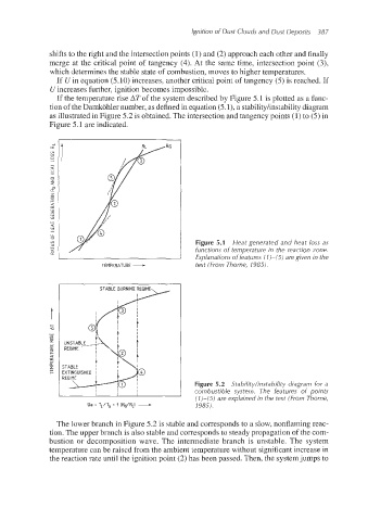
shifts to the right and the intersection points (1) and (2) approach each other and finally
merge at the critical point of tangency (4). At the same time, intersection point (3),
which determines the stable state of combustion, moves to higher temperatures.
If e/ in equation (5.10) increases, another critical point of tangency (5)is reached. If
U increases further, ignition becomes impossible.
If the temperature rise AT of the system described by Figure 5.1 is plotted as a func-
tion of the Damkohler number, as defined in equation (5-1),a stabilityhnstabilitydiagram
as illustrated in Figure 5.2 is obtained.The intersection and tangency points (1)to (5)in
Figure 5.1 ape indicated.
Figure 5.1 Heat generated and heat loss as
TEMPERATURE - functions of temperature in the reaction zone.
Explanations of features (7)-(5) are given in the
text (From Thorne, 1985).
STABLE BURNING REGIME
REGIME
Figure 5.2 Stability/instability diagram for a
I I I I I combustible system. The features of points
(1)-(5) are explained in the text (From Thorne,
Oa = TL/TG = f (RG/RLl + 1985).
The lower branch in Figure 5.2 is stable and corresponds to a slow, nonflaming reac-
tion. The upper branch is also stable and corresponds to steady propagation of the com-
bustion or decomposition wave. The intermediate branch is unstable. The system
temperature can be raised from the ambient temperature without significant increase in
the reaction rate until the ignition point (2) has been passed. Then, the systemjumps to