
Page 516 - Dust Explosions in the Process Industries
P. 516
Assessment of @itability 483
1
DUST DISPERSER
OLENOID VALVE
DUST COLLECTING
PLATFORM
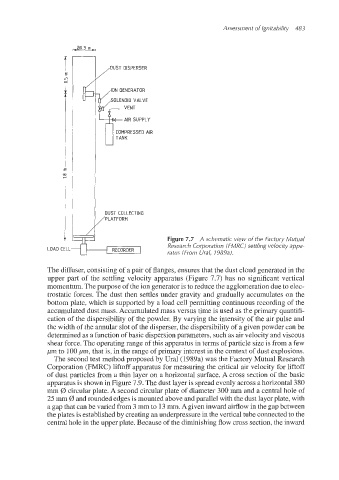
Figure 7.7 A schematic view of the Factory Mutual
I RECORDER I Rgsearch Corporation (FMRC) settling velocky appa-
LOAD CELL ratus (From Ural, 1989ai.
The diffuser, consisting of a pair of flanges, ensures that the dust cloud generated in the
upper part of the settling velocity apparatus (Figure 7.7) has no significant vertical
momentum.The purpose of the ion generatoris to reduce the agglomeration due to elec-
trostatic forces. The dust then settles under gravity and gradually accumulates on the
bottom plate, which is supported by a load cell permitting continuous recording of the
accumulated dust mass. Accumulated mass versus time is used as the primary quantifi-
cation of the dispersibility of the powder. By varying the intensity of the air pulse and
the width of the annular slot of the disperser,the dispersibilityof a given powder can be
determined as a function of basic dispersionparameters, such as air velocity and viscous
shear force. The (operatingrange of this apparatus in terms of particle size is from a few
pm to 100pm, that is, in the range of primary interest in the context of dust explosions.
The second test method proposed by Urd (1989a) was the Factory Mutual Research
Corporation (MRC) liftoff apparatus for measuring the critical air velocity for liftoff
of dust particles from a thin layer on a horizontal surface. A cross section of the basic
apparatusis shown in Figure 7.9. The dust layer is spread evenly across a horizontal 380
mm 0 circular plate. A second circular plate of diameter 300 mm and a central hole of
25 mm (b and rounded edges is mounted above and parallel with the dust layer plate, with
a gap that can be varied from 3 mm to 13mm. A given inward airflow in the gap between
the plates is established by creating an underpressure in the vertical tube connected to the
central.hole in the upper plate. Because of the diminishing flow cross section, the inward