
Page 110 - Dynamics and Control of Nuclear Reactors
P. 110
104 CHAPTER 8 Reactor control
WATER IN
DESIRED LEVEL
VALVE ACTUATOR
WATER OUT
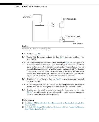
FIG. 8.10
Problem 8.4, a water level control system.
8.2. Verify Eq. (8.10).
8.3. Verify that the system defined by Eq. (8.17) becomes oscillatory for
K i > 0.0001.
8.4. An example of a feedback control action is shown in Fig. 8.10. The objective is
to maintain the level of water in a tank. The water level is measured by a level
gauge and the controller adjusts the valve based on the error between the set
point (desired) value of the level and the actual (measured) level. The flow out
of the tank is allowed to change, so that the water in the tank is maintained at a
desired level. Develop a block diagram of the tank level control system show-
ing the system, controller, measurement, and actuator function.
8.5. Explain why two of the cases shown in Fig. 8.8 experience a prompt jump and
one case does not.
8.6. Formulate equations for a zero-power reactor with proportional and integral
control. Use the one-delay group model for neutronics. Define all terms.
8.7. Explain why the initial response to a reactivity disturbance (as shown in
Fig. 8.7) is so different for an integral controller then the response for propor-
tional or proportional plus integral control.
References
[1] C.L. Phillips, J.M. Parr, Feedback Control Systems, fifth ed., Prentice Hall, Upper Saddle
River, NJ, 2011.
[2] R.C. Dorf, R.H. Bishop, Modern Control Systems, twelfth ed., Prentice Hall-Pearson,
Upper Saddle River, NJ, 2011.