
Page 173 - Dynamics and Control of Nuclear Reactors
P. 173
170 CHAPTER 13 Boiling water reactors
STEAM DRYER LIFTING LUG
VENT AND HEAD SPRAY
STEAM DRYER
ASSEMBLY
STEAM OUTLET
STEAM SEPARATOR
ASSEMBLY
CORE SPRAY INLET FEEDWATER INLET
FEEDWATER SPARGER
LOW PRESSURE COOLANT
INJECTION INLET
CORE SPRAY LINE
CORE SPRAY SPARGER
TOP GUIDE
JET PUMP ASSEMBLY
CORE SHROUD
FUEL ASSEMBLIES CONTROL BLADE
CORE PLATE
JET PUMP/RECIRCULATION
WATER INLET
RECIRCULATION
WATER OUTLET
VESSEL SUPPORT SKIRT
SHIELD WALL
CONTROL ROD DRIVES
CONTROL ROD DRIVE
HYDRAULIC LINES
IN-CORE FLUX MONITOR
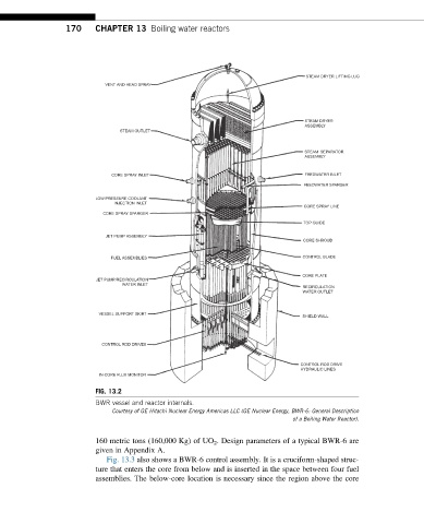
FIG. 13.2
BWR vessel and reactor internals.
Courtesy of GE Hitachi Nuclear Energy Americas LLC (GE Nuclear Energy, BWR-6: General Description
of a Boiling Water Reactor).
160 metric tons (160,000 Kg) of UO 2 . Design parameters of a typical BWR-6 are
given in Appendix A.
Fig. 13.3 also shows a BWR-6 control assembly. It is a cruciform-shaped struc-
ture that enters the core from below and is inserted in the space between four fuel
assemblies. The below-core location is necessary since the region above the core