
Page 172 - Dynamics and Control of Nuclear Reactors
P. 172
13.3 Characteristics of BWRs 169
Containment
Cooling System
Steam Line
Reactor Vessel
Turbine
Generator
Separators
& Dryers Heater
Condenser
Feedwater
3
Condensate
Core Pumps
1 & 2
Feed
Pumps
Control
Rods
Demineralizer
Recirculation Pumps
Emergency Water
Supply Systems
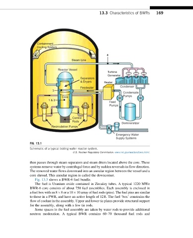
FIG. 13.1
Schematic of a typical boiling water reactor system.
U.S. Nuclear Regulatory Commission: www.nrc.gov/reactors/bwrs.html.
then passes through steam separators and steam driers located above the core. These
systems remove water by centrifugal force and by sudden reversals in flow direction.
The removed water flows downward into an annular region between the vessel and a
core shroud. This annular region is called the downcomer.
Fig. 13.3 shows a BWR-6 fuel bundle.
The fuel is Uranium oxide contained in Zircaloy tubes. A typical 1220 MWe
BWR-6 core consists of about 750 fuel assemblies. Each assembly is enclosed in
a fuel box with an 8 8or a 10 10 array of fuel rods (pins). The fuel pins are similar
to those in a PWR, and have an active length of 12ft. The fuel ‘box’ constrains the
flow of coolant in the assembly. Upper and lower tie plates provide structural support
for the assembly, along with a few tie rods.
Some spaces in the fuel assembly are taken by water rods to provide additional
neutron moderation. A typical BWR contains 60–70 thousand fuel rods and